
Page 370 - Programmable Logic Controllers, Fifth Edition - Mobile version
P. 370
L1 Inputs Ladder logic program Output
Position_1_Switch Position_2_Switch L2
<Local:1:I.Data.1> <Local:1:I.Data.2> Internal_Relay
Position_1_Switch Room_Light L
Position_2_Switch Position_1_Switch
<Local:1:I.Data.2> <Local:1:I.Data.1>
Position_2_Switch
Position_3_Switch Room_Light
Internal_Relay <Local:1:I.Data.3> <Local:2:O.Data.5>
Position_3_Switch Position_3_Switch
<Local:1:I.Data.3> Internal_Relay
Monitor Tags Window
Name Value Force Mask Style Data Type
Internal_Relay 0 Decimal BOOL
Position_1_Sw... 0 Decimal BOOL
Position_2_Sw... 0 Decimal BOOL
Position_3_Sw... 0 Decimal BOOL
Room_Light 0 Decimal BOOL
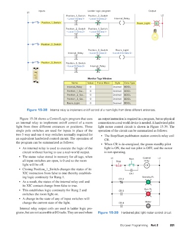
Figure 15-38 Internal relay to implement on/off control of a room light from three different entrances.
Figure 15-38 shows a ControlLogix program that uses an output instruction is required in a program, but no physical
an internal relay to implement on/off control of a room connection to a real world device is needed. A hardwired pilot
light from three different entrances or positions. Three light motor control circuit is shown in Figure 15-39. The
single pole switches are used for inputs in place of the operation of the circuit can be summarized as follows:
two 3-way and one 4-way switches normally required for • The Stop/Start pushbutton station controls relay coil
an equivalent hardwired control circuit. The operation of CR.
the program can be summarized as follows:
• When CR is de-energized, the green standby pilot
• An internal relay is used to execute the logic of the light is ON, the red run pilot is OFF, and the motor
circuit without having to use a real-world output. is not operating.
• The status value stored in memory for all tags, when L1 Control L2
all input switches are open, is 0 and so the room Stop Start relay
light will be off. CR
• Closing Position_1_Switch changes the status of its
XIC instruction from false to true thereby establish- CR-1
ing logic continuity for Rung 1. Standby PL
CR-2
• As a result, the status of the internal relay coil and G
its XIC contact change from false to true.
• This establishes logic continuity for Rung 2 and CR-3 Run PL
switches the room light on. R
• A change in the state of any of input switches will
change the current state of the light. CR-4 Motor
M
Internal relay output coils are used in ladder logic pro-
grams, but are not accessible at I/O racks. They are used where Figure 15-39 Hardwired pilot light motor control circuit
Bit-Level Programming Part 2 351
pet73842_ch15_333-394.indd 351 03/11/15 7:33 PM