
Page 369 - Programmable Logic Controllers, Fifth Edition - Mobile version
P. 369
Monitor Tags window, when the motor is operating. When
ward contactor coil is connected in series with the
the motor is operating: • The normally closed contact controlled by the for-
reverse coil.
• The XIC Motor_Start instruction is false because
the NO start button is open; therefore its value is 0. • The normally closed contact controlled by the
• The XIC Motor_Stop instruction is true because the reverse contactor coil is connected in series with the
NC stop button is closed; therefore its value is 1. forward coil.
• The OTE Motor_Run instruction is true because the • When the forward coil is energized, the normally
rung has logic continuity; therefore its value is 1. closed contact in series with the reverse coil is
opened to prevent the reverse coil from being
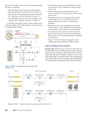
A hardwired reversing conveyor motor control circuit energized.
is shown in Figure 15-36. The operation of the circuit can • When the reverse coil is energized, the normally
be summarized as follows: closed contact in series with the forward coil opens
to prevent the forward coil from being energized.
Three-phase Workpiece
reversing motor • To reverse the motor with this control circuit, the
Forward Reverse operator must press the stop button to de-energize
the respective coil, reclosing the respective normally
Conveyor
closed contact.
A B • Figure 15-37 shows the reversing starter circuit
H1 H3H2 H4 implemented using an RSLogix 5000 controller.
Internal Relay Instructions
X1 120 V X2 Internal relay instructions are used when other than real-
Forward
Stop R OL world field devices are needed as input or output reference
F instructions. For example, an internal relay bit is used as an
Stop
output when the logical resultant of a rung is used to control
F
Forward Reverse other internal logic. An internal control relay is programmed
F in the ControlLogix system by creating a tag (either program
Reverse R or controller type) and assigning a Boolean type to the tag.
R
Figure 15-36 Hardwired reversing conveyor motor
control circuit.
Inputs Ladder logic program Outputs
L1 L2
Stop_button Forward_button Reverse_coil Forward_Coil
<Local:1:I.Data.0> <Local:1:I.Data.1> <Local:2:O.Data.1> <Local:2:O.Data.0>
Stop_button Forward_Coil F
Forward_button Forward_Coil Reverse_Coil R
<Local:2:O.Data.0>
Reverse_button
Stop Stop_button Reverse_button Forward_Coil Reverse_coil Reversing contactors
<Local:1:I.Data.0> <Local:1:I.Data.2> <Local:2:O.Data.0> <Local:2:O.Data.1>
Forward
Reverse Reverse_coil
<Local:2:O.Data.1>
Figure 15-37 Programmed reversing conveyor motor control circuit.
350 Part 2 Bit-Level Programming
pet73842_ch15_333-394.indd 350 03/11/15 7:33 PM