
Page 364 - Programmable Logic Controllers, Fifth Edition - Mobile version
P. 364
Part 2 Bit-Level
Programming
Input tag data base
Field input Ladder logic
Part Objectives devices program
After completing this part, you will be able to:
PLC PLC
• Know what happens during the program scan input processor
• Demonstrate an understanding of input, output, and module
internal relay addressing format for a tag-based Logix
controller
• Develop ladder logic programs with input instructions Field Field output
and output coil combinations power devices
• Develop ladder logic programs with latched outputs supply
Output tag PLC M
data base output
module
Program Scan Field power
supply
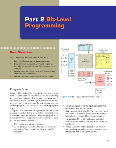
When a CLX controller executes a program, it must
know—in real time—when external devices controlling Figure 15-26 Logix controller operating cycle.
a process are changing. During each operating cycle,
the processor reads all the inputs, takes these values,
and energizes or de-energizes the outputs according to
the user program. This process is known as the program • The status signals from the inputs are sent to the
scan. input tags where they are stored.
Figure 15-26 illustrates the signal flow into and out of • As the program is scanned by the processor, inputs
a Logix controller during a controller’s operating cycle are checked for True or False conditions and the
when ladder logic is executing. During the program scan, ladder logic is evaluated based on these values.
the controller reads rungs and branches from left to right • The resulting ON or OFF action, as a result of
and top to bottom as follows:
evaluating each rung, is then sent to the output tags
• Only one rung at a time is scanned. for storage.
• As the program is scanned, the status of inputs are • During the output update portion of the scan, cor-
checked for True (1 or ON) or False (0 or OFF) responding output values are sent to the process or
conditions. machine by way of the output module.
345
pet73842_ch15_333-394.indd 345 03/11/15 7:33 PM