
Page 365 - Programmable Logic Controllers, Fifth Edition - Mobile version
P. 365
• I/O updates occur asynchronously to the scan
of the logic. With a ControlLogix processor two • When a rung has only one output instruction it will
always be true.
separate 32-bit unsynchronized processes go on • The last instruction on a rung must always be an
simultaneously—that is, asynchronously. This output instruction.
means that the module can update the input tag • The XIC, or Examine If Closed contact instruction,
from the field and write the output tag to the checks to see if the input has a value of one. If the
field at any point (or at several points) during the input is one, the XIC instruction returns a true value.
processor’s execution of the ladder rungs. The • The XIO, or Examine If Open contact instruction,
result is more efficiency and control over when the checks to see if the input has a value of zero. If the
input field device data are updated in the input tag input is zero, the XIO instruction returns a true value.
and when the output data resulting from the solved
logic are sent to the output modules and their • The OTE or Output Energize coil instruction sets
respective field devices. the tag associated with it to true or one when the
rung has logic continuity. When true it can be used
to energize an output device or simply set a value in
Creating Ladder Logic memory to one.
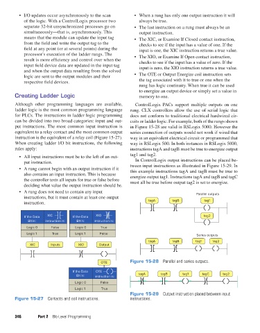
Although other programming languages are available, ControlLogix PACs support multiple outputs on one
ladder logic is the most common programming language rung. CLX controllers allow the use of serial logic that
for PLCs. The instructions in ladder logic programming does not conform to traditional electrical hardwired cir-
can be divided into two broad categories: input and out- cuits or ladder logic. For example, both of the rungs shown
put instructions. The most common input instruction is in Figure 15-28 are valid in RSLogix 5000. However the
equivalent to a relay contact and the most common output series connection of outputs would not work if wired that
instruction is the equivalent of a relay coil (Figure 15-27). way in an equivalent electrical circuit or programmed that
When creating ladder I/O bit instructions, the following way in RSLogix 500. In both instances in RSLogix 5000,
rules apply: instructions tagA and tagB must be true to energize output
• All input instructions must be to the left of an out- tag1 and tag2.
put instruction. In ControlLogix output instructions can be placed be-
• A rung cannot begin with an output instruction if it tween input instructions as illustrated in Figure 15-29. In
this example instructions tagA and tagB must be true to
also contains an input instruction. This is because energize output tag1. Instructions tagA and tagB and tagC
the controller tests all inputs for true or false before must all be true before output tag2 is set to energize.
deciding what value the output instruction should be.
• A rung does not need to contain any input Parallel outputs
instructions, but it must contain at least one output
instruction. tagA tagB tag1
If the Data XIC If the Data XIO tag2
Bit is: instruction is: Bit is: instruction is:
Logic 0 False Logic 0 True
Logic 1 True Logic 1 False
Series outputs
tagA tagB tag1 tag2
XIC Inputs XIO Output
OTE Figure 15-28 Parallel and series outputs.
If the Data OTE
Bit is: instruction is: tagA tagB tag1 tagC tag2
Logic 0 False
Logic 1 True
Figure 15-29 Output instruction placed between input
Figure 15-27 Contacts and coil instructions. instructions.
346 Part 2 Bit-Level Programming
pet73842_ch15_333-394.indd 346 03/11/15 7:33 PM