
Page 367 - Programmable Logic Controllers, Fifth Edition - Mobile version
P. 367
Initially, all program development can proceed with just
the tag names and data types assigned. Using tag aliases, L1 L2
programmers can write code independent of electrical
connection assignments. At a later date, input and output
field devices are easily matched to the pin numbers on the Motor Motor Motor
run
stop
start
respective module they are connected to.
M
Adding Ladder Logic to the Contactor coil
Main Routine Contactor auxiliary
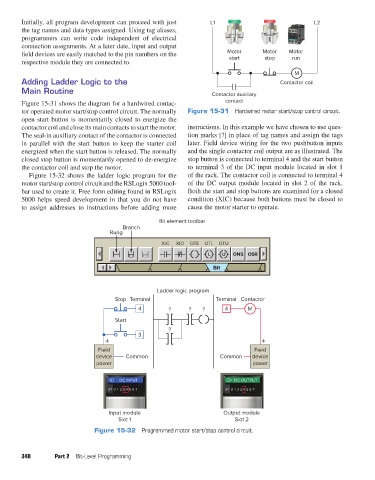
Figure 15-31 shows the diagram for a hardwired contac- contact
tor operated motor start/stop control circuit. The normally Figure 15-31 Hardwired motor start/stop control circuit.
open start button is momentarily closed to energize the
contactor coil and close its main contacts to start the motor. instructions. In this example we have chosen to use ques-
The seal-in auxiliary contact of the contactor is connected tion marks [?] in place of tag names and assign the tags
in parallel with the start button to keep the starter coil later. Field device wiring for the two pushbutton inputs
energized when the start button is released. The normally and the single contactor coil output are as illustrated. The
closed stop button is momentarily opened to de-energize stop button is connected to terminal 4 and the start button
the contactor coil and stop the motor. to terminal 3 of the DC input module located in slot 1
Figure 15-32 shows the ladder logic program for the of the rack. The contactor coil is connected to terminal 4
motor start/stop control circuit and the RSLogix 5000 tool- of the DC output module located in slot 2 of the rack.
bar used to create it. Free form editing found in RSLogix Both the start and stop buttons are examined for a closed
5000 helps speed development in that you do not have condition (XIC) because both buttons must be closed to
to assign addresses to instructions before adding more cause the motor starter to operate.
Bit element toolbar
Branch
Rung
XIC XIO OTE OTL OTU
L U ONS OSR
Bit
Ladder logic program
Stop Terminal Terminal Contactor
4 ? ? ? 4 M
Start
?
3
+ +
Field Field
device Common Common device
power power
DC INPUT DC OUTPUT
ST 01 23 45 67 ST 01 23 45 67
Input module Output module
Slot 1 Slot 2
Figure 15-32 Programmed motor start/stop control circuit.
348 Part 2 Bit-Level Programming
pet73842_ch15_333-394.indd 348 03/11/15 7:33 PM