
Page 368 - Programmable Logic Controllers, Fifth Edition - Mobile version
P. 368
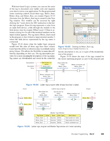
With text-based Logix systems you can use the name
                   of the tag to document your ladder code and organize         New Tag
                   your data to mirror your application. For the programmed     Name:      Motor_Start
                   motor start/stop control circuit three tags, Motor_Start,    Description:     Start button for
                   Motor_Stop, and Motor_Run, are created. Figure  15-33                           motor
                   illustrates how the Motor_Start tag is created in the New
                   Tag window.  This window can be accessed by right                       Alias
                   clicking the ? mark above the XIC instruction in the lad-               Local:1:I.Data
                   der logic program. Since this tag represents a value from                 Name         Data Type
                   an input field device, a link through the module to the                   +  Local:1:C  AB:1756_DO:C:0
                   field device must be created. When Local:1:I.Data is se-                  –  Local:1:I  AB:1756_DO:I:0
                   lected a dialog box for all of the terminal numbers on the                   Local:1:I.Fault  DINT
                   input module appears. The tag name (Motor_Start) used                        Local:1:I.Data
                   in the program is then linked to input terminal number 3                    0  1  2  3  4  5  6  7
                                                                                                 9 10 11 12
                                                                                               8
                   where the field device represented by the tag name is                      16 17 18 19 20  13 14 15
                                                                                                           21 22 23
                   connected.                                                                 24 25 26 27 28  29 30 31
                     Figure 15-34 shows what the ladder logic program
                   would look like after all three tags have been created.   Figure 15-33  Creating the Motor_Start tag.
                   Users have the ability to reference data via multiple names   Source: Image Courtesy of Rockwell Automation, Inc.
                   using Aliases. This allows the flexibility to name data dif-  but the description is not, as it is part of the documenta-
                   ferently depending on their use. The tag description pro-  tion of the project.
                   vides for a more meaningful description of the tag name.   Figure 15-35 shows the state of the tags created for
                   Tag names are downloaded and stored in the controller   the motor start/stop program as seen in the program and

                                      Description      Start button for  Stop button for
                                                          motor             motor       Motor contactor coil
                                      Tag Name          Motor_Start      Motor_Stop        Motor_Run
                                          Alias       <Local:1:I.Data.3>  <Local:1:I.Data.4>  <Local:2:O.Data.4>


                                                     Motor contactor coil
                                                        Motor_Run
                                                     <Local:2:O.Data.4>


                                      Figure 15-34  Ladder logic program after all tags have been created.

                                  Inputs                          Ladder logic program                  Output
                                                   Start button for  Stop button for
                            L1                        motor            motor       Motor contactor coil          L2
                                                    Motor_Start      Motor_Stop       Motor_Run
                                                  <Local:1:I.Data.3>  <Local:1:I.Data.4>  <Local:2:O.Data.4>
                                   Motor_Stop                                                       Motor_Run  M

                                                 Motor contactor coil
                                   Motor_Start       Motor_Run
                                                  <Local:2:O.Data.4>
                              Stop
                                                                                                        Contactor
                              Start                             Monitor Tags Window

                                                 Tag Name  Value  Style  Data Type   Description
                                                Motor_Start  0   Decimal  BOOL   Start button for motor
                                                Motor_Stop   1   Decimal  BOOL   Stop button for motor
                                                Motor_Run    1   Decimal  BOOL   Motor contactor coil
                            Figure 15-35  Ladder logic program and Monitor Tags window with motor operating.


                                                                                        Bit-Level Programming  Part 2   349


          pet73842_ch15_333-394.indd   349                                                                              03/11/15   7:33 PM