
Page 371 - Programmable Logic Controllers, Fifth Edition - Mobile version
P. 371
L1 Inputs Ladder logic program Outputs L2
Motor_Stop Motor_Start
<Local:1:I.Data.0> <Local:1:I.Data.1> Internal_Relay_CR Standby_PL G
Motor_Stop
Motor_Start Internal_Relay_CR Run_PL R
Standby_PL
Stop
Internal_Relay_CR <Local:2:O.Data.0>
Motor
Start
Run_PL
Internal_Relay_CR <Local:2:O.Data.1>
Motor
Internal_Relay_CR <Local:2:O.Data.2>
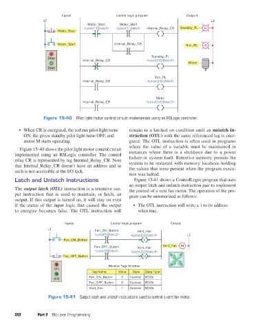
Figure 15-40 Pilot light motor control circuit implemented using an RSLogix controller.
• When CR is energized, the red run pilot light turns remain in a latched on condition until an unlatch in-
ON, the green standby pilot light turns OFF, and struction (OTU) with the same referenced tag is ener-
motor M starts operating. gized. The OTL instruction is often used in programs
where the value of a variable must be maintained in
Figure 15-40 shows the pilot light motor control circuit
implemented using an RSLogix controller. The control instances where there is a shutdown due to a power
relay CR is represented by tag Internal_Relay_CR. Note failure or system fault. Retentive memory permits the
that Internal_Relay_CR doesn’t have an address and as system to be restarted with memory locations holding
such is not accessible at the I/O rack. the values that were present when the program execu-
tion was halted.
Latch and Unlatch Instructions Figure 15-41 shows a ControlLogix program that uses
an output latch and unlatch instruction pair to implement
The output latch (OTL) instruction is a retentive out- the control of a vent fan motor. The operation of the pro-
put instruction that is used to maintain, or latch, an gram can be summarized as follows:
output. If this output is turned on, it will stay on even
if the status of the input logic that caused the output • The OTL instruction will write a 1 to its address
to energize becomes false. The OTL instruction will when true.
Inputs Ladder logic program Output
L1 Fan_ON_Button Vent_Fan
<Local:1:I.Data.2> <Local:2:O.Data.4> L2
Fan_ON_Button L
Fan_OFF_Button Vent_Fan Vent_Fan M
<Local:1:I.Data.3> <Local:2:O.Data.4>
Fan_OFF_Button U
Monitor Tags Window
ON
Tag Name Value Style Data Type
Fan_ON_Button 0 Decimal BOOL
OFF
Fan_OFF_Button 0 Decimal BOOL
Vent_Fan 1 Decimal BOOL
Figure 15-41 Output latch and unlatch instructions used to control a vent fan motor.
352 Part 2 Bit-Level Programming
pet73842_ch15_333-394.indd 352 03/11/15 7:33 PM