
Page 381 - Programmable Logic Controllers, Fifth Edition - Mobile version
P. 381
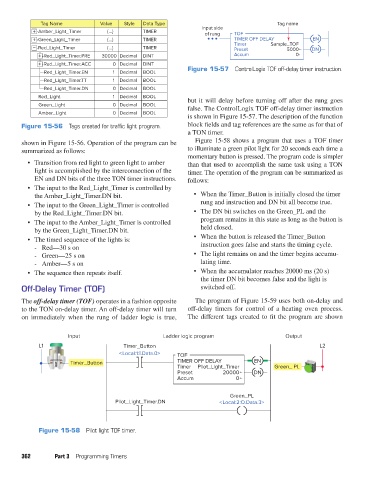
Tag Name           Value   Style  Data Type                                 Tag name
                                                                          Input side
                    -Amber_Light_Timer     {…}         TIMER               of rung  TOF
                    -Green_Light_Timer     {…}         TIMER                        TIMER OFF DELAY           EN
                                                                                    Timer       Sample_TOF
                    -Red_Light_Timer       {…}         TIMER                        Preset            5000    DN
                      -Red_Light_Timer.PRE  30000 Decimal  DINT                     Accum                0
                      -Red_Light_Timer.ACC   0  Decimal  DINT
                       Red_Light_Timer.EN    1  Decimal  BOOL        Figure 15-57  ControlLogix TOF off-delay timer instruction.
                       Red_Light_Timer.TT    1  Decimal  BOOL
                       Red_Light_Timer.DN    0  Decimal  BOOL
                     Red_Light               1  Decimal  BOOL        but it will delay before turning off after the rung goes
                     Green_Light             0  Decimal  BOOL        false. The ControlLogix TOF off-delay timer instruction
                     Amber_Light             0  Decimal  BOOL
                                                                     is shown in Figure 15-57. The description of the function
               Figure 15-56  Tags created for traffic light program.  block fields and tag references are the same as for that of
                                                                     a TON timer.
               shown in Figure 15-56. Operation of the program can be   Figure 15-58 shows a program that uses a TOF timer
               summarized as follows:                                to illuminate a green pilot light for 20 seconds each time a
                                                                     momentary button is pressed. The program code is simpler
                 •  Transition from red light to green light to amber   than that used to accomplish the same task using a TON
                    light is accomplished by the interconnection of the   timer. The operation of the program can be summarized as
                    EN and DN bits of the three TON timer instructions.  follows:
                 •  The input to the Red_Light_Timer is controlled by
                    the Amber_Light_Timer.DN bit.                      •  When the Timer_Button is initially closed the timer
                 •  The input to the Green_Light_Timer is controlled      rung and instruction and DN bit all become true.
                    by the Red_Light_Timer.DN bit.                     •  The DN bit switches on the Green_PL and the
                 •  The input to the Amber_Light_Timer is controlled      program remains in this state as long as the button is
                    by the Green_Light_Timer.DN bit.                      held closed.
                 •  The timed sequence of the lights is:               •  When the button is released the Timer_Button
                      - Red—30 s on                                       instruction goes false and starts the timing cycle.
                      - Green—25 s on                                  •  The light remains on and the timer begins accumu-
                      - Amber—5 s on                                      lating time.
                 •  The sequence then repeats itself.                  •  When the accumulator reaches 20000 ms (20 s)
                                                                          the timer DN bit becomes false and the light is
               Off-Delay Timer (TOF)                                      switched off.

               The off-delay timer (TOF) operates in a fashion opposite   The program of Figure 15-59 uses both on-delay and
               to the TON on-delay timer. An off-delay timer will turn   off-delay timers for control of a heating oven process.
               on immediately when the rung of ladder logic is true,   The different tags created to fit the program are shown


                               Input                         Ladder logic program                    Output
                     L1                          Timer_Button                                                   L2
                                               <Local:1:I.Data.0>  TOF
                               Timer_Button                       TIMER OFF DELAY          EN
                                                                  Timer  Pilot_Light_Timer        Green_ PL
                                                                  Preset         20000     DN
                                                                  Accum              0

                                                                                   Green_PL
                                              Pilot_Light_Timer.DN              <Local:2:O.Data.3>


                     Figure 15-58  Pilot light TOF timer.


               362        Part 3  Programming Timers


          pet73842_ch15_333-394.indd   362                                                                              03/11/15   7:33 PM