
Page 386 - Programmable Logic Controllers, Fifth Edition - Mobile version
P. 386
PART 3 REVIEW QUESTIONS
1. Compare the methods used to address timers in an 8. What number would be entered into the PRE value
SLC 500 and a ControlLogix controller. of a ControlLogix timer for a timing period of
2. List the five different members of a TIMER 4.5 minutes?
structure. 9. Compare the operation a TOF and a TON timer.
3. What type of timing application may require you to 10. When does the rung of a TOF timer begin accumu-
use a TON on-delay timer? lating time?
4. What PRE value is used for a timer? 11. The RTO timer is a retentive timer. Explain what
5. To what value is the accumulated value of a timer this means.
normally set? 12. How are the retentive timer and reset instruction
6. What timer status bit is set to 1 when the TON related?
timer times out?
7. The TON instruction is self-resetting. Explain what
this means.
PART 3 PROBLEMS
1. Modify the original CLX ten-second TON timer pro- 5. With reference to the CLX limit switch RTO pro-
gram (Figure 15-52) with an additional rung added gram (Figure 15-62), in addition to the alarm, you
to the program that will energize a solenoid when- are required to install a warning pilot light to indi-
ever the timer is enabled and timing. The solenoid is cate that the timer has timed out. How would you
to be connected to pin 6 of the digital output module. proceed?
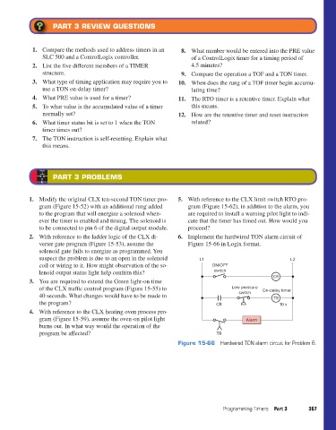
2. With reference to the ladder logic of the CLX di- 6. Implement the hardwired TON alarm circuit of
verter gate program (Figure 15-53), assume the Figure 15-66 in Logix format.
solenoid gate fails to energize as programmed. You
suspect the problem is due to an open in the solenoid L1 L2
coil or wiring to it. How might observation of the so- ON/OFF
lenoid output status light help confirm this? switch
CR
3. You are required to extend the Green light-on time
of the CLX traffic control program (Figure 15-55) to Low pressure On-delay timer
40 seconds. What changes would have to be made to switch TR
the program? CR 10 s
4. With reference to the CLX heating oven process pro-
gram (Figure 15-59), assume the oven-on pilot light Alarm
burns out. In what way would the operation of the
program be affected? TR
Figure 15-66 Hardwired TON alarm circuit for Problem 6.
Programming Timers Part 3 367
pet73842_ch15_333-394.indd 367 03/11/15 7:33 PM