
Page 387 - Programmable Logic Controllers, Fifth Edition - Mobile version
P. 387
Part 4 Programming
Counters
Counters Part Objectives
Counters are similar to timers, except that a counter ac-
cumulates (counts) the changes in state of an external After completing this part, you will be able to:
trigger signal whereas timers increment using an internal • Understand ControlLogix counter tags and their
clock. PLC counters are generally triggered by a change members
in an input field device that causes a false-to-true transi- • Utilize status bits from counters in logic
tion of the counter ladder rung. It does not matter how • Develop ladder logic programs using ControlLogix
long the rung stays true or false—it is only the transition counters
that counts.
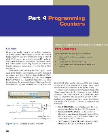
There are two basic counter types: count-up (CTU) and
count-down (CTD). The ControlLogix CTU instruction
and counter selection toolbar are shown in Figure 15-67.
When you want to use a counter, you must create a tag of
type COUNTER (it is a predefined data type) and enter
the preset and the accumulated value. When entering the accumulated values can be entered. A RES reset instruc-
instruction, this tag must be defined before the preset and tion that has the same tag name as the counter must be used
to reset the accumulated value of the counter to zero.
All counters are retentive in that the accumulated value
of any counter is retained, even during a power failure,
TON TOF RTO CTU CTD RES until reset. The on/off status of the counter done, over-
flow, and underflow bits are retentive as well. Control-
Favorites Add-On Alarms Bit Timer/Counter
Logix counter parameters and status bits are shown in the
Tag name edit tags window of Figure 15-68 and can be summarized
True CTU as follows:
False Count Up CU
Counter Package_Counter • Preset (PRE) Value—Specifies the value the coun-
Preset 24 DN ter must reach before the done (DN) bit turns on (1).
Accum 0
Input side of rung • Accumulated (ACC) Value—Is the number of
false-to-true transitions of the counter rung. ACC is
Package_Counter reset to zero when a reset (RES) instruction (of the
RES same counter address) is executed.
• CU (Count-Up Enable Bit)—The count-up enable
Figure 15-67 CTU count-up counter instruction. bit indicates the CTU instruction is enabled.
368
pet73842_ch15_333-394.indd 368 03/11/15 7:33 PM