
Page 384 - Programmable Logic Controllers, Fifth Edition - Mobile version
P. 384
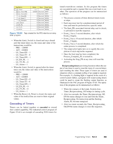
Tag Name          Value   Style  Data Type      timed event-driven routines. In this program the timers
                          -LS_Timer           {…}        TIMER           are cascaded in such a manner that one event leads to an-
                            -LS_Timer.PRE   120000 Decimal  DINT         other. The operation of the program can be summarized
                            -LS_Timer.ACC       0 Decimal  DINT          as follows:
                            LS_Timer.EN         0 Decimal  BOOL
                            LS_Timer.TT         0 Decimal  BOOL            •  The process consists of three distinct timed events
                            LS_Timer.DN         0 Decimal  BOOL              or steps.
                          Limit_Switch          0 Decimal  BOOL            •  Each step must last for a predetermined period of
                          LS_EN_PL              0 Decimal  BOOL              time and must be performed in a specific order.
                          LS_TT_PL              0 Decimal  BOOL            •  The Start_PB, associated internal relay seal-in circuit,
                          LS_Alarm              0 Decimal  BOOL
                                                                             is activated to start the sequence.
                   Figure 15-63  Tags created for the RTO retentive on-delay   •  Event_1 has a 3 second duration, after which
                   timer program.                                            Event_2 begins.

                                                                           •  Event_2 has a 10 second duration, after which
                     •  When the Limit_Switch is closed and stays closed     Event _3 begins.
                       until the timer times out, the status and value of the   •  Event_3 has a 5 second duration, after which the
                       instructions would be:                                entire process is completed.
                          - PRE – 120000
                          - ACC –120000                                    •  The output pilot lights turn on to signify the com-
                          - LS_Timer.EN – 1                                  pletion of each step in the sequence.
                          - LS_Timer.TT – 0                                •  Once the final step has been completed, the
                          - LS_Timer.DN – 1                                  Process_Complete_PL is turned on.
                          - LS_EN_PL – 1                                   •  Activating the Stop_PB at any time will reset the
                          - LS_TT_PL – 0                                     process.
                          - LS_Alarm – 1                                   Reciprocating timers are timing functions where the out-
                     •  When the Limit_Switch is opened after the timer   put of one timer is used to reset the input of a second timer,
                       times out, the status and value of the instructions   each resetting the other. These types of timers are used in
                       would be:                                         situations where a constant cycling of an output is required.
                          - PRE – 120000                                 For example, if a flashing light is required in the event of a
                          - ACC –120000                                  control system failure, a program with reciprocating timers
                          - LS_Timer.EN – 0                              could be used to create the flashing output function, as
                          - LS_Timer.TT – 0                              illustrated in the PAC program of Figure 15-65. The opera-
                          - LS_Timer.DN – 1                              tion of the program can be summarized as follows:
                          - LS_EN_PL – 0
                          - LS_TT_PL – 0                                   •  When the contacts of the Limit_Switch close,
                          - LS_Alarm – 1                                     Timer_Reciprocationg_Off beings its timing cycle.
                     •  When the Reset_LS_Timer is closed, the status and   •  After two seconds, the Timer_Reciprocationg_Off.
                       value of the instructions are reset to their original   DN bit status changes to true and both the Timer_
                       values.                                               Reciprocating_On instruction and the flashing
                                                                             Alarm_PL become energized.
                   Cascading of Timers                                     •  After two more seconds, the Timer_Reciprocating_

                   Timers can be linked together or  cascaded to extend      On.DN bit status changes to reset the sequence.
                   their control capability. The industrial control program of
                   Figure 15-64 is an example of cascading TON timers for


                                                                                         Programming Timers  Part 3     365


          pet73842_ch15_333-394.indd   365                                                                              03/11/15   7:33 PM