
Page 411 - Programmable Logic Controllers, Fifth Edition - Mobile version
P. 411
Restart_Button Ladder logic
<Local:1:I.Data.1> Counter_1
RES
Enter_Limit_Sw
<Local:1:I.Data.3>
CTU
Count Up CU
L1 Inputs Counter Counter_1
Preset 50 DN
Accum 0
Restart_Button
Exit_Limit_Sw
<Local:1:I.Data.4>
CTD
Count Down CD
Counter Counter_1
Preset 50 DN
Enter_Limit_Sw 0 Output L2
Accum
Conveyor_Contactor Conveyor_Contactor C
Counter_1.DN <Local:2:O.Data.2>
Exit_Limit_Sw
FBD equivalent
CTUD_01
CTUD ... BNOT_01
Count Up/Down BNOT ...
0 0
Enter_Limit_Sw CUEnable ACC ACC Boolean Not
0 0 1
Exit_Limit_Sw CDEnable DN In Out Conveyor_Contactor
50
50 PRE
Reset
0
Restart_Button
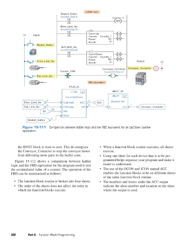
Figure 15-111 Comparison between ladder logic and the FBD equivalent for an Up/Down counter
application.
the BNOT block is reset to zero. This de-energizes • When a function block routine executes, all sheets
the Conveyor_Contactor to stop the conveyor motor execute.
from delivering more parts to the buffer zone. • Using one sheet for each device that is to be pro-
Figure 15-112 shows a comparison between ladder grammed helps organize your program and make it
logic and the FBD equivalent for the program used to test easier to understand.
the accumulated value of a counter. The operation of the • The use of the OCON and ICON named ACC
FBD can be summarized as follows: enables the function blocks to be on different sheets
of the same function block routine.
• The function block routine is broken into four sheets. • The numbers and letters under the ACC output
• The order of the sheets does not affect the order in indicate the sheet number and location on the sheet
which the function blocks execute. where the output is used.
392 Part 6 Function Block Programming
pet73842_ch15_333-394.indd 392 03/11/15 7:34 PM