
Page 408 - Programmable Logic Controllers, Fifth Edition - Mobile version
P. 408
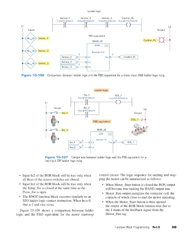
Ladder logic
                                                Sensor_1     Sensor_2      Sensor_3     Caution_PL
                                             <Local:1:I.Data.1>  <Local:1:I.Data.2>  <Local:1:I.Data.3> <Local:2:O.Data.4>

                      L1                                                                                              L2
                           Inputs                                                                              Output

                                                                  FBD equivalent
                                 Sensor_1
                                                                     BAND_01                          Caution_PL
                                                                      BAND   ...

                                 Sensor_2
                                                                    Boolean And
                                                            0                    0
                                                 Sensor_1         In1        Out         Caution_PL
                                                            0
                                                 Sensor_2         In2
                                 Sensor_3
                                                            0
                                                 Sensor_3         In3
                      Figure 15-106  Comparison between ladder logic and the FBD equivalent for a three-input AND ladder logic rung.


                                                                      Ladder logic
                                                               Sw_1                SOL_1
                                                           <Local:1:I.Data.3>  <Local:2:O.Data.4>
                                      L1
                                            Inputs             Sw_2                                   L2
                                                           <Local:1:I.Data.4>
                                                 Sw_1                                           Output

                                                                                              SOL_1
                                                                     FBD equivalent

                                                 Sw_2                   BOR_01
                                                                         BOR   ...
                                                              0        Boolean Or   0
                                                      Sw_1          In1        Out         SOL_1
                                                              0
                                                      Sw_2          In2


                                      Figure 15-107  Comparison between ladder logic and the FBD equivalent for a
                                      two-input OR ladder logic rung.


                     •  Input In2 of the BOR block will be true only when   control circuit. The logic sequence for starting and stop-
                       all three of the sensor switches are closed.      ping the motor can be summarized as follows:
                     •  Input In1 of the BOR block will be true only when   •  When Motor_Start button is closed the BOR output
                       the Temp_Sw is closed at the same time as the         will become true making the BAND output true.
                       Press_Sw is open.                                   •  Motor_Run output energizes the contactor coil, the
                     •  The BNOT function block executes similarly to an     contacts of which close to start the motor operating.
                       XIO ladder logic contact instruction. When In is 0,   •  When the Motor_Start button is then opened
                       Out is 1 and vice versa.                              the output of the BOR block remains true due to
                     Figure 15-109 shows a comparison between ladder         the 1 status of the feedback signal from the
                   logic and the FBD equivalent for the motor start/stop     Motor_Run tag.


                                                                                   Function Block Programming  Part 6   389


          pet73842_ch15_333-394.indd   389                                                                              03/11/15   7:34 PM