
Page 404 - Programmable Logic Controllers, Fifth Edition - Mobile version
P. 404
Click to open properties box
Tag_Name
BAND ... Properties - Tag_Name
Boolean And
1 0 Parameters Tag
In 1 Out
1 In 2 Vis Name Type Description
1 Value
In 3 I EnableIn 1 BOOL Enable Input. If false, the instru...
1
In 4 I In1 1 BOOL Boolean Input to the instruction.
I In2 1 BOOL Boolean Input to the instruction.
I In3 1 BOOL Boolean Input to the instruction.
I In4 1 BOOL Boolean Input to the instruction.
I In5 1 BOOL Boolean Input to the instruction.
I In6 1 BOOL Boolean Input to the instruction.
I In7 1 BOOL Boolean Input to the instruction.
I In8 1 BOOL Boolean Input to the instruction.
O EnableOut 0 BOOL Enable Output.
O Out 0 BOOL The result of ANDing all eight
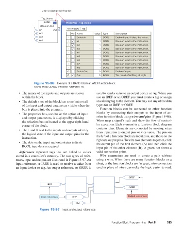
Figure 15-96 Example of a BAND (Boolean AND) function block.
Source: Image Courtesy of Rockwell Automation, Inc.
• The names of the inputs and outputs are shown used to send a value to an output device or tag. When you
within the block. use an IREF or an OREF you must create a tag or assign
• The default view of the block has some but not all an existing tag to the element. You may use any of the data
of the input and output parameters visible when the types for an IREF or OREF.
box is placed into the program. Function blocks can be connected to other function
• The properties box, used to set the option of input blocks by connecting their outputs to the input of an-
and output parameters, is displayed by clicking other function block using wires and pins (Figure 15-98).
the selection button located at the upper right hand Wires map a signal’s path and show the flow of control-
corner of the block. ler execution. Each element in a function block diagram
• The 1 and 0 next to the inputs and outputs identify contains pins. Elements are connected by moving wires
the logical state of the input and output pins for the from input pins to output pins or vice versa. The pins on
instruction. the left of a function block are input pins, and those on the
right are output pins. To wire two elements together, click
• The dots on the input and output pins indicate the output pin of the first element (A) and then click the
BOOL type data is required. input pin of the other element (B). A green dot shows a
References represent tags that are linked to values valid connection point.
stored in a controller’s memory. The two types of refer- Wire connectors are used to create a path without
ences, input and output, are illustrated in Figure 15-97. An using a wire. When there are many function blocks on a
input reference, or IREF, is used to receive a value from sheet, or the function blocks are far apart, wire connectors
an input device or tag. An output reference, or OREF, is used in place of wires can make the logic easier to read.
OREF
IREF
OREF
Input references IREF Output references
IREF
Figure 15-97 Input and output references.
Function Block Programming Part 6 385
pet73842_ch15_333-394.indd 385 03/11/15 7:34 PM