
Page 401 - Programmable Logic Controllers, Fifth Edition - Mobile version
P. 401
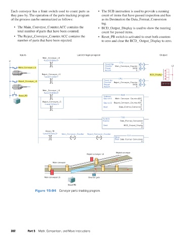
Each conveyor has a limit switch used to count parts as
               they pass by. The operation of the parts tracking program   •  The SUB instruction is used to provide a running
                                                                          count of items that have passed inspection and has
               of the process can be summarized as follows:               as its Destination the Data_Format_Conversion
                                                                          tag.
                 •  The Main_Conveyor_Counter.ACC contains the         •  BCD_Output_Display is used to show the running
                    total number of parts that have been counted.         count for passed items.
                 •  The Reject_Conveyor_Counter.ACC contains the       •  Reset_PB switch is activated to reset both counters
                    number of parts that have been rejected.              to zero and clear the BCD_ Output_Display to zero.


                     Inputs                               Ladder logic program                                 Output
                                    Main_Conveyor_LS
              L1                    <Local:1:I.Data.0>                               CTU
                                                                            Count Up               CU
                                                                            Counter  Main_Conveyor_Counter            L2
                    Main_Conveyor_LS                                        Preset           5000  DN
                                                                            Accum               0
                                   Reject_Conveyor_LS                                                    BCD_Display
                                     <Local:1:I.Data.1>
                                                                                     CTU
                    Reject_Conveyor_LS                                     Count Up  Reject_Conveyor_Counter  CU
                                                                           Counter
                                                                           Preset            5000  DN            00 0 0
                                                                           Accum                0
                                    Main_Conveyor_LS
                                    <Local:1:I.Data.0>
                    Reset_PB                                               Subtract   SUB
                                                                           Source A  Main_Conveyor_Counter.ACC
                                                                                                   0
                                    Reject_Conveyor_LS                     Source B  Reject_Conveyor_Counter.ACC
                                     <Local:1:I.Data.1>                                            0
                                                                           Dest      Data_Format_Conversion
                                                                                                   0
                                                                                      TOD
                                                                          To BCD
                                                                          Source     Data_Format_Conversion
                                                                                                   0
                                                                           Dest         BCD_Output_Display
                                                                                                   0
                                      Reset_PB
                                    <Local:1:I.Data.2>  Main_Conveyor_Counter  Reject_Conveyor_Counter
                                                                                          CLR
                                                      RES              RES        Clear
                                                                                  Dest  Data_Format_Conversion
                                                                                                   0

                                                                                   Reject conveyor
                                                                Reject conveyor LS

                                          Main conveyor


                                     Main conveyor LS            Diverter gate

                                                    Reset PB
                               Figure 15-94  Conveyor parts tracking program.


               382        Part 5  Math, Comparison, and Move Instructions


          pet73842_ch15_333-394.indd   382                                                                              03/11/15   7:34 PM