
Page 405 - Programmable Logic Controllers, Fifth Edition - Mobile version
P. 405
Wiring elements
...
A B
Output Input Output
pin pin Output Wire Input
pin pin pin
Input
pins
Wire Wire
Output
pin
Figure 15-98 Function block diagram wire and pins.
• Each output wire connector must have at least one
Input wire connector corresponding input wire connector.
Output wire connector • Each output wire connector requires a unique tag
Speed name and the corresponding input connector must
ICON
Speed have the same name.
OCON • Multiple input wire connectors can reference
the same output wire connector. This lets you
share data at several points in your function block
diagram.
Sheet 1 Sheet 2
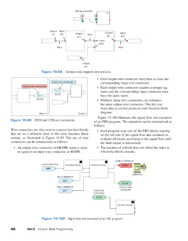
Figure 15-100 illustrates the signal flow and execution
Figure 15-99 OCON and ICON wire connectors. of an FBD program. The operation can be summarized as
follows:
Wire connectors are also used to connect function blocks • Each program scan sets all the FBD blocks starting
that are on a different sheet of the same function block on the left side of the signal flow and continues to
routine, as illustrated in Figure 15-99. The use of wire evaluate all blocks according to the signal flow until
connectors can be summarized as follows: the final output is determined.
• An output wire connector, or OCON, sends a value • The location of a block does not affect the order in
or signal to an input wire connector, or ICON. which the blocks execute.
Output reference
Input reference Function block Function block OREF
IREF
Solenoid
Input reference
IREF
OCON
Input reference Output wire
IREF Input wire connector
connector
ICON
Function block
Figure 15-100 Signal flow and execution of an FBD program.
386 Part 6 Function Block Programming
pet73842_ch15_333-394.indd 386 03/11/15 7:34 PM