
Page 407 - Programmable Logic Controllers, Fifth Edition - Mobile version
P. 407
Block 1 ... Block 2 ... Block 3 ... execute from the JSR instruction. No subroutine or return
subroutine instruction in the FBD is necessary.
Function block programs are similar to ladder logic
programs, except that the process is visualized in the form
Feedback loop
of function blocks instead of ladder rungs. Figure 15-106
Assume Data shows a comparison between ladder logic and the FBD
Available indicator
equivalent for a three-input AND ladder logic rung. The
Figure 15-104 Assume Data Available indicator marker. operation of the FBD can be summarized as follows:
• When the inputs represented by Sensor_1, Sensor_2,
FBD Programming and Sensor_3 are true (value 1) the BAND (Boolean
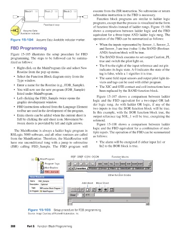
Figure 15-105 illustrates the setup procedure for FBD AND) function block will be true.
programming. The steps to be followed can be summa- • The BAND block executes to set output Caution_PL
rized as follows: true and switch the pilot light on.
• The 0 to the right of the input reference and out pin
• Right click on the MainProgram file and select New indicates its logic state. A 0 indicates the state of the
Routine from the pop-up menu. tag is false, while a 1 signifies it is true.
• Select the Function Block diagram entry from the • The same field input sensors and output pilot light de-
Type window. vices and tags can be used with either program.
• Enter a name for the Routine (e.g., FDB_Sample). • The XIC and OTE contact and coil instructions have
• You will now see the new program (FDB_Sample) been replaced by the BAND function block.
listed under MainProgram.
• Left clicking the FBD_Sample twice opens the Figure 15-107 shows a comparison between ladder
graphic development window. logic and the FBD equivalent for a two-input OR lad-
• FBD instructions selected from the Language Element der logic rung. As with ladder OR logic, if any of the
two inputs is true the BOR function block will be true.
toolbar are used in the development of the program. In this example, with the BOR function block true, the
• Extra sheets can be added when the current sheet is output reference tag SOL_1 will be true, energizing the
full by clicking the add sheet icon. Movement be- solenoid.
tween sheets is provided by left and right arrows. Figure 15-108 shows a comparison between ladder
logic and the FBD equivalent for a combination of mul-
The MainRoutine is always a ladder logic program in tiple inputs. The operation of the FBD can be summarized
RSLogix 5000 software, and all other routines are called as follows:
from the MainRoutine. Therefore, the MainRoutine will
have one unconditional rung with a jump to subroutine • The alarm will be energized if either input In1 or
(JSR) calling FBD_Sample. The FBD program will In2 to the BOR block is true.
IREF OREF ICON OCON Function blocks
MainProgram
Program Tags
MainRoutine
FBD_Sample
Other function blocks
Add sheet Move Sheet
Figure 15-105 Setup procedure for FDB programming.
Source: Image Courtesy of Rockwell Automation, Inc.
388 Part 6 Function Block Programming
pet73842_ch15_333-394.indd 388 03/11/15 7:34 PM