
Page 403 - Programmable Logic Controllers, Fifth Edition - Mobile version
P. 403
Part 6 Function Block
Programming
Function Block Diagram (FBD)
A function block diagram (FBD) is a graphical depic- Part Objectives
tion of process flow using simple and complex intercon-
necting blocks. It is similar to a ladder logic diagram, After completing this part, you will be able to:
except that function blocks replace the interconnec-
tion of contacts and the coils. In addition, there are no • Describe the difference between ladder logic and
power rails. function block diagram programming
A function block circuit is analogous to an electrical • Recognize the basic elements of a function block
circuit where links and wires depict signal paths between diagram
components. The workplace is known as a sheet and con- • Write and read a function block diagram
sists of function blocks joined together with lines called
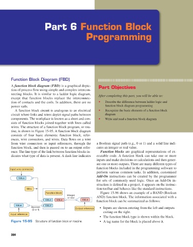
wires. The structure of a function block program, or rou-
tine, is shown in Figure 15-95. A function block diagram
consists of four basic elements: function block, refer-
ences, wire connectors, and wires. Data flows on a wire
from wire connectors or input references, through the a Boolean signal path (e.g., 0 or 1) and a solid line indi-
function block, and then is passed on to an output refer- cates an integer or real value.
ence. The line type of the link between function blocks in- Function blocks are graphical representations of ex-
dicates what type of data is present. A dash line indicates ecutable code. A function block can take one or more
inputs and make decisions or calculations and then gener-
ate one or more outputs. There are many different types of
Input wire connector function blocks included in the programming software to
perform various common tasks. In addition, customized
Add-On instructions can be created by the programmer
Value
for sets of commonly used logic. Once an Add-On in-
struction is defined in a project, it appears on the instruc-
Wire tion toolbar and behaves like the standard instructions.
Function block Figure 15-96 shows an example of a BAND (Boolean
Integer AND) function block. The information associated with a
or real
Value Value Value function block can be summarized as follows:
Value Value
Boolean Output reference • Inputs are shown entering from the left and outputs
(0 or 1)
exiting on the right.
Input reference
• The function block type is shown within the block.
Figure 15-95 Structure of function block or routine. • A tag name for the block is placed above it.
384
pet73842_ch15_333-394.indd 384 03/11/15 7:34 PM