
Page 406 - Programmable Logic Controllers, Fifth Edition - Mobile version
P. 406
to view block properties
... Click this buttom
Start_PB
IREF
Figure 15-101 IREF is latched for the scan of the function
block routine.
Parameters* Tag
• The inputs of a block require data to be available
before the controller can execute that block. Vis Name Value Type
• If function blocks are not wired together, it does not I Enableln 1 BOOL
matter which block executes first as there is no data I I SourceA 0.0 REAL
SourceB
REAL
flow between the blocks.
• The interconnected line between the blocks indi- Figure 15-102 Using the Parameters tab to show
cates what type of signal is present. or hide a pin.
Source: Image Courtesy of Rockwell Automation, Inc.
Data latching refers to how the controller verifies that
the data present at the input to a function block are valid.
If you use an IREF to specify input data for a function • Select the Vis check box to show the pin.
block instruction, as illustrated in Figure 15- 101, the data • Click OK.
in that IREF are latched (won’t change) for the scan of
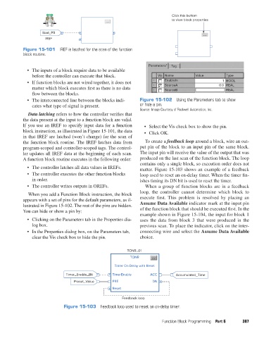
the function block routine. The IREF latches data from To create a feedback loop around a block, wire an out-
program-scoped and controller-scoped tags. The control- put pin of the block to an input pin of the same block.
ler updates all IREF data at the beginning of each scan. The input pin will receive the value of the output that was
A function block routine executes in the following order: produced on the last scan of the function block. The loop
contains only a single block, so execution order does not
• The controller latches all data values in IREFs. matter. Figure 15-103 shows an example of a feedback
• The controller executes the other function blocks loop used to reset an on-delay timer. When the timer fin-
in order. ishes timing its DN bit is used to reset the timer.
• The controller writes outputs in OREFs. When a group of function blocks are in a feedback
loop, the controller cannot determine which block to
When you add a Function Block instruction, the block
appears with a set of pins for the default parameters, as il- execute first. This problem is resolved by placing an
lustrated in Figure 15-102. The rest of the pins are hidden. Assume Data Available indicator mark at the input pin
You can hide or show a pin by: of the function block that should be executed first. In the
example shown in Figure 15-104, the input for block 1
• Clicking on the Parameters tab in the Properties dia- uses the data from block 3 that were produced in the
log box. previous scan. To place the indicator, click on the inter-
• In the Properties dialog box, on the Parameters tab, connecting wire and select the Assume Data Available
clear the Vis check box to hide the pin. choice.
TONR_01
TONR
Timer On Delay with Reset
Timer_Enable_Bit TimerEnable ACC Accumulated_Time
Preset_Value PRE DN
Reset
Feedback loop
Figure 15-103 Feedback loop used to reset an on-delay timer.
Function Block Programming Part 6 387
pet73842_ch15_333-394.indd 387 03/11/15 7:34 PM