Page 557 - Handbook of Modern Telecommunications
P. 557
4-88                    CRC Handbook of Modern Telecommunications, Second Edition


                                              Peering Point

                                          PE Router A
                                                     PE Router B


                              Provider A                          Provider B


                                       Admin. Server A
                                                    Admin. Server B

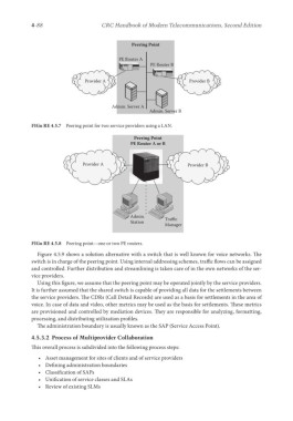
            FIGu RE 4.5.7  Peering point for two service providers using a LAN.

                                               Peering Point
                                              PE Router A or B


                             Provider A                           Provider B


                                              Admin.      Traffic
                                              Station
                                                          Manager

            FIGu RE 4.5.8  Peering point—one or two PE routers.

              Figure 4.5.9 shows a solution alternative with a switch that is well known for voice networks. The
            switch is in charge of the peering point. Using internal addressing schemes, traffic flows can be assigned
            and controlled. Further distribution and streamlining is taken care of in the own networks of the ser-
            vice providers.
              Using this figure, we assume that the peering point may be operated jointly by the service providers.
            It is further assumed that the shared switch is capable of providing all data for the settlements between
            the service providers. The CDRs (Call Detail Records) are used as a basis for settlements in the area of
            voice. In case of data and video, other metrics may be used as the basis for settlements. These metrics
            are provisioned and controlled by mediation devices. They are responsible for analyzing, formatting,
            processing, and distributing utilization profiles.
              The administration boundary is usually known as the SAP (Service Access Point).
            4.5.3.2  Process of Multiprovider Collaboration
            This overall process is subdivided into the following process steps:

              •   Asset management for sites of clients and of service providers
              •   Defining administration boundaries
              •   Classification of SAPs
              •   Unification of service classes and SLAs
              •   Review of existing SLMs

