


Page 1037 - Basic Electrical Engineering
P. 1037
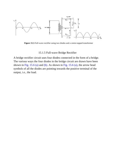
Figure 15.5 Full-wave rectifier using two diodes and a centre-tapped transformer


                                          15.1.5 Full-wave Bridge Rectifier


               A bridge rectifier circuit uses four diodes connected in the form of a bridge.
               The various ways the four diodes in the bridge circuit are drawn have been

               shown in Fig. 15.6 (a) and (b). As shown in Fig. 15.6 (a), the arrow head
               symbols of all the diodes are pointing towards the positive terminal of the

               output, i.e., the load.

