


Page 1038 - Basic Electrical Engineering
P. 1038
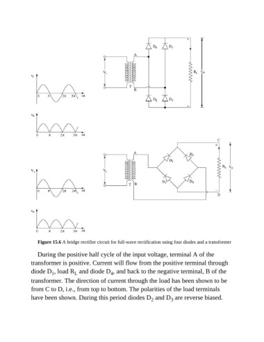
Figure 15.6 A bridge rectifier circuit for full-wave rectification using four diodes and a transformer

                  During the positive half cycle of the input voltage, terminal A of the
               transformer is positive. Current will flow from the positive terminal through

               diode D , load R  and diode D , and back to the negative terminal, B of the
                         1
                                    L
                                                    4
               transformer. The direction of current through the load has been shown to be
               from C to D, i.e., from top to bottom. The polarities of the load terminals
               have been shown. During this period diodes D  and D  are reverse biased.
                                                                                3
                                                                       2

