


Page 1077 - Basic Electrical Engineering
P. 1077
1, i.e., when both the diodes output X will be 1. If A = 1 and B = i.e., when
               will be in forward biased Condition, the output X will be 1.
                  Although two diodes have been used to show an OR gate, in actual

               practice OR function is obtained using a transistor–transistor logic (TTL).
               The 2-input OR gates is available in the TTL 74 xx series. 7432 is a 2-input

               TTL OR gate integrated circuit. The IC chip has four OR gates.


                                                    16.5.3 AND Gate

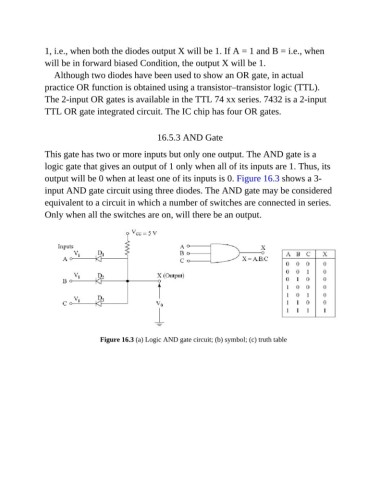
               This gate has two or more inputs but only one output. The AND gate is a

               logic gate that gives an output of 1 only when all of its inputs are 1. Thus, its
               output will be 0 when at least one of its inputs is 0. Figure 16.3 shows a 3-

               input AND gate circuit using three diodes. The AND gate may be considered
               equivalent to a circuit in which a number of switches are connected in series.

               Only when all the switches are on, will there be an output.


                                 Figure 16.3 (a) Logic AND gate circuit; (b) symbol; (c) truth table

