


Page 1074 - Basic Electrical Engineering
P. 1074
16.5 LOGIC GATES

               A logic gate is a simple device used to make digital integrated circuits.
               Diodes and transistors are used to perform switching functions in logic gates.

               Logic gates basically have one or more inputs and only one output. The
               output of the gate depends upon the way the inputs are applied and they are

               named as AND gate, OR gate, NOT gate, etc. Logic gates may be classified
               into two categories; combinational type (with no memory) and sequential

               type (with memory).
                  In digital circuits or systems there are two possible states or conditions. A

               switch may be closed or open, i.e., on or off. These two conditions may be
               represented by 1 and 0, respectively. The two logic levels, i.e., 1 and 0
               represent, respectively, voltage high or voltage low. Logic systems can be

               positive or negative. In positive logic voltage high is represented by 1 and
               voltage low is represented by 0. In negative logic, voltage high is 0 and

               voltage low is 1. Binary number system may be used to represent the states.
               In a digital system, analog quantities are first converted to digital forms using

               the binary code. After the signal is processed, it is again converted into
               analog form for display.

                  The possible states or conditions in digital systems are expressed as 1 and
               0. The closed switch or the existence of a signal may be called 1 and open
               switch or non existence of a signal may be called 0. 1 and 0 are referred to as

               binary numbers. As mentioned earlier, in decimal system we have 0 to 9 as
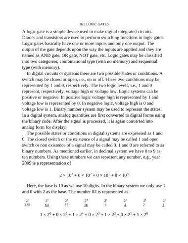
               ten numbers. Using these numbers we can represent any number, e.g., year

               2009 is a representation of

                                                                       1
                                               3
                                                           2
                                        2 × 10  + 0 × 10  + 0 × 10  + 9 × 10       0
                  Here, the base is 10 as we use 10 digits. In the binary system we only use 1
               and 0 with 2 as the base. The number 82 is represented as


                                                                 3
                                                                                      1
                                                                           2
                                 6
                                            5
                                                      4
                           1 × 2  + 0 × 2  + 1 × 2  + 0 × 2  + 1 × 2  + 0 × 2  + 1 × 2          0

