


Page 1142 - Basic Electrical Engineering
P. 1142
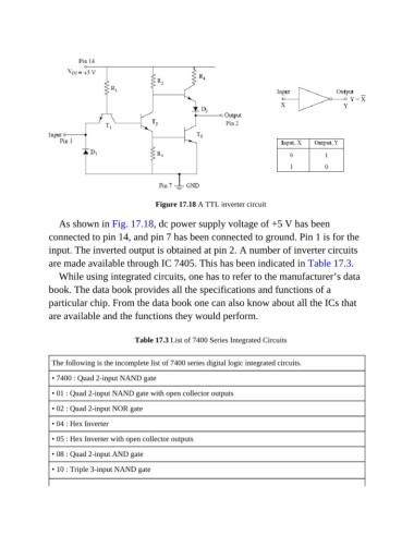
Figure 17.18 A TTL inverter circuit


                  As shown in Fig. 17.18, dc power supply voltage of +5 V has been
               connected to pin 14, and pin 7 has been connected to ground. Pin 1 is for the

               input. The inverted output is obtained at pin 2. A number of inverter circuits
               are made available through IC 7405. This has been indicated in Table 17.3.
                  While using integrated circuits, one has to refer to the manufacturer’s data

               book. The data book provides all the specifications and functions of a
               particular chip. From the data book one can also know about all the ICs that

               are available and the functions they would perform.

                                         Table 17.3 List of 7400 Series Integrated Circuits


                The following is the incomplete list of 7400 series digital logic integrated circuits.
                • 7400 : Quad 2-input NAND gate

                • 01 : Quad 2-input NAND gate with open collector outputs

                • 02 : Quad 2-input NOR gate

                • 04 : Hex Inverter

                • 05 : Hex Inverter with open collector outputs

                • 08 : Quad 2-input AND gate
                • 10 : Triple 3-input NAND gate

