
Page 310 - Basic Electrical Engineering
P. 310
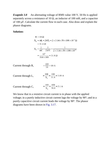
Exapmle 3.8     An alternating voltage of RMS value 100 V, 50 Hz is applied
               separately across a resistance of 10 Ω, an inductor of 100 mH, and a capacitor
               of 100 μF. Calculate the current flow in each case. Also draw and explain the

               phasor diagrams.


               Solution:


               Current through R,


               Current through L,


               Current through C,


               We know that in a resistive circuit current is in phase with the applied

               voltage; in a purely inductive circuit current lags the voltage by 90°; and in a
               purely capacitive circuit current leads the voltage by 90°. The phasor

               diagrams have been shown in Fig. 3.17.