
Page 313 - Basic Electrical Engineering
P. 313
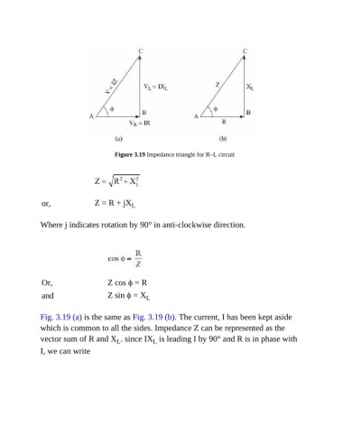
Figure 3.19 Impedance triangle for R–L circuit


                or,                Z = R + jX   L


               Where j indicates rotation by 90° in anti-clockwise direction.


                Or,                    Z cos ϕ = R

                and                    Z sin ϕ = X   L


               Fig. 3.19 (a) is the same as Fig. 3.19 (b). The current, I has been kept aside

               which is common to all the sides. Impedance Z can be represented as the
               vector sum of R and X . since IX  is leading I by 90° and R is in phase with
                                           L
                                                        L
               I, we can write