Page 311 - Basic Electrical Engineering
P. 311

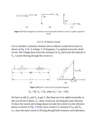
Figure 3.17 Phasor diagrams (a) resistive circuit; (b) purely inductive circuit; (c) purely capacitive
                                                           circuit


                                                3.2.2 L–R Series Circuit


               Let us consider a resistance element and an inductor connected in series as
               shown in Fig. 3.18. A voltage, V of frequency, f is applied across the whole

               circuit. The voltage drop across the resistance is V  and across the inductor is
                                                                            R
               V . Current flowing through the circuit is I.
                  L


                                       Figure 3.18 (a) R–L series circuit; (b) phasor diagram

                                     V  = IR, V  = IX  where X  = ωL = 2πfL
                                                  L
                                                          L
                                                                      L
                                       R
               We have to add V  and V  to get V. But these are to be added vectorially as
                                     R
                                               L
               they are all not in phase, i.e., these vectors are not along the same direction.
               To draw the current and voltage phasor we take the current I as the reference
               phasor as shown in Fig. 3.18 (b), since current I is common to V  and V ,
                                                                                             R
                                                                                                      L
               i.e., since the same current is flowing through both resistance and inductance.
   306   307   308   309   310   311   312   313   314   315   316