
Page 487 - Basic Electrical Engineering
P. 487
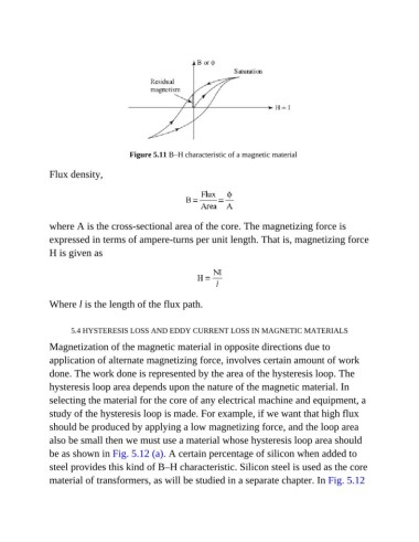
Figure 5.11 B–H characteristic of a magnetic material

               Flux density,


               where A is the cross-sectional area of the core. The magnetizing force is
               expressed in terms of ampere-turns per unit length. That is, magnetizing force

               H is given as


               Where l is the length of the flux path.


                      5.4 HYSTERESIS LOSS AND EDDY CURRENT LOSS IN MAGNETIC MATERIALS

               Magnetization of the magnetic material in opposite directions due to
               application of alternate magnetizing force, involves certain amount of work

               done. The work done is represented by the area of the hysteresis loop. The
               hysteresis loop area depends upon the nature of the magnetic material. In
               selecting the material for the core of any electrical machine and equipment, a

               study of the hysteresis loop is made. For example, if we want that high flux
               should be produced by applying a low magnetizing force, and the loop area

               also be small then we must use a material whose hysteresis loop area should
               be as shown in Fig. 5.12 (a). A certain percentage of silicon when added to

               steel provides this kind of B–H characteristic. Silicon steel is used as the core
               material of transformers, as will be studied in a separate chapter. In Fig. 5.12