
Page 568 - Basic Electrical Engineering
P. 568
= V + I R″ cos ϕ + DF cos (90 − ϕ)
e
2
2
= V + I R″ cos ϕ + I X″ sin ϕ
2
2
e
2
e
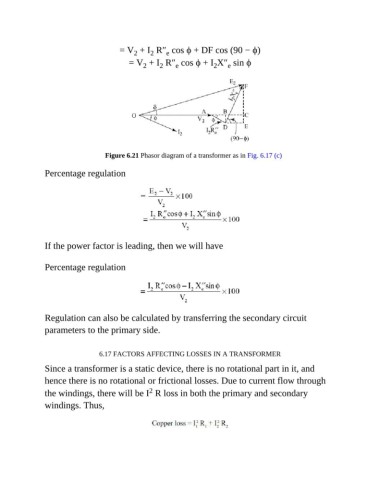
Figure 6.21 Phasor diagram of a transformer as in Fig. 6.17 (c)
Percentage regulation
If the power factor is leading, then we will have
Percentage regulation
Regulation can also be calculated by transferring the secondary circuit
parameters to the primary side.
6.17 FACTORS AFFECTING LOSSES IN A TRANSFORMER
Since a transformer is a static device, there is no rotational part in it, and
hence there is no rotational or frictional losses. Due to current flow through
2
the windings, there will be I R loss in both the primary and secondary
windings. Thus,