
Page 697 - Basic Electrical Engineering
P. 697
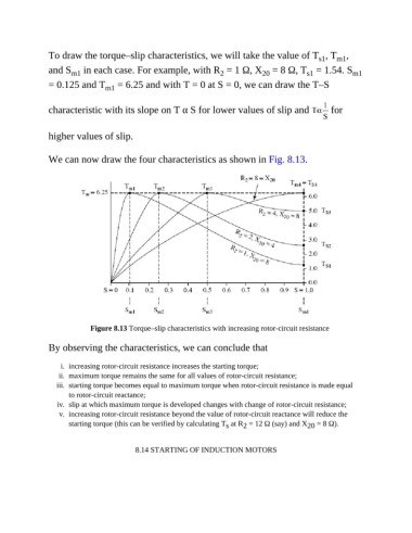
To draw the torque–slip characteristics, we will take the value of T , T ,
                                                                                                     m1
                                                                                                s1
               and S  in each case. For example, with R  = 1 Ω, X  = 8 Ω, T  = 1.54. S                    m1
                                                                               20
                                                                                            s1
                      m1
                                                                  2
               = 0.125 and T  = 6.25 and with T = 0 at S = 0, we can draw the T–S
                                m1
               characteristic with its slope on T α S for lower values of slip and                  for


               higher values of slip.


               We can now draw the four characteristics as shown in Fig. 8.13.


                            Figure 8.13 Torque–slip characteristics with increasing rotor-circuit resistance


               By observing the characteristics, we can conclude that


                   i.  increasing rotor-circuit resistance increases the starting torque;
                  ii.  maximum torque remains the same for all values of rotor-circuit resistance;
                  iii.  starting torque becomes equal to maximum torque when rotor-circuit resistance is made equal
                     to rotor-circuit reactance;
                  iv.  slip at which maximum torque is developed changes with change of rotor-circuit resistance;
                   v.  increasing rotor-circuit resistance beyond the value of rotor-circuit reactance will reduce the
                     starting torque (this can be verified by calculating T  at R  = 12 Ω (say) and X  = 8 Ω).
                                                                    s
                                                                                            20
                                                                         2
                                         8.14 STARTING OF INDUCTION MOTORS