


Page 857 - Basic Electrical Engineering
P. 857
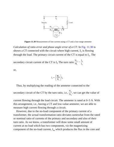
Figure 11.30 Measurement of line current using a CT and a low-range ammeter

               Calculation of ratio error and phase angle error of a CT: In Fig. 11.30 is
               shown a CT connected with the circuit where high current, I  is flowing
                                                                                        1
               through the load. The primary circuit current of the CT is equal to I . The
                                                                                                1


               secondary circuit current of the CT is I  The turn ratio
                                                              2


               or,


                  Thus, by multiplying the reading of the ammeter connected to the


               secondary circuit of the CT by the turn ratio, i.e.,           , we can get the value of


               current flowing through the load circuit. The ammeter is rated at 0–5 A. With
               this arrangement, i.e., having a CT and low-value ammeter, we are able to

               measure high current flowing through a circuit.
                  However, due to the no-load component of the primary current of a

               transformer, the actual transformation ratio deviates somewhat from the rated
               or nominal ratio of currents of the primary and secondary and also of their

               turn ratio. As we know, a transformer will draw some small amount of
               current at no load which has two components, viz the magnetizing
               component of the no-load current, I  which produces the flux in the core and
                                                          m

