


Page 858 - Basic Electrical Engineering
P. 858
the loss component, I  of the primary current, I  which corresponds to the
                                                                        0
                                         c
               losses in the core of the transformer. For the purpose of analysis, we will
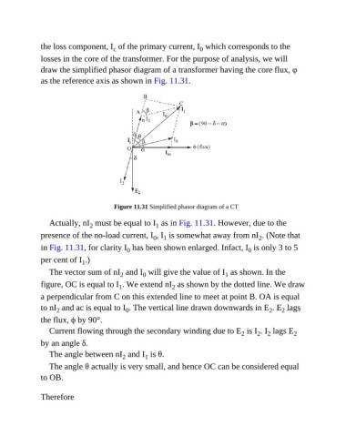
               draw the simplified phasor diagram of a transformer having the core flux, φ
               as the reference axis as shown in Fig. 11.31.


                                         Figure 11.31 Simplified phasor diagram of a CT


                  Actually, nI  must be equal to I  as in Fig. 11.31. However, due to the
                                 2
                                                        1
               presence of the no-load current, I , I  is somewhat away from nI . (Note that
                                                           1
                                                                                             2
                                                       0
               in Fig. 11.31, for clarity I  has been shown enlarged. Infact, I  is only 3 to 5
                                              0
                                                                                         0
               per cent of I .)
                              1
                  The vector sum of nI  and I  will give the value of I  as shown. In the
                                                                                 1
                                            2
                                                    0
               figure, OC is equal to I . We extend nI  as shown by the dotted line. We draw
                                                              2
                                           1
               a perpendicular from C on this extended line to meet at point B. OA is equal
               to nI  and ac is equal to I . The vertical line drawn downwards in E . E  lags
                                                                                                2
                                                                                                     2
                                             0
                     2
               the flux, ϕ by 90°.
                  Current flowing through the secondary winding due to E  is I . I  lags E               2
                                                                                      2
                                                                                                2
                                                                                            2
               by an angle δ.
                  The angle between nI  and I  is θ.
                                            2
                                                    1
                  The angle θ actually is very small, and hence OC can be considered equal
               to OB.

               Therefore

