


Page 862 - Basic Electrical Engineering
P. 862
An analog multimeter is basically a permanent magnet moving coil
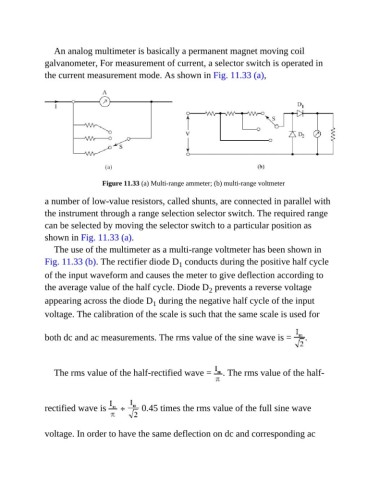
               galvanometer, For measurement of current, a selector switch is operated in
               the current measurement mode. As shown in Fig. 11.33 (a),


                                  Figure 11.33 (a) Multi-range ammeter; (b) multi-range voltmeter


               a number of low-value resistors, called shunts, are connected in parallel with
               the instrument through a range selection selector switch. The required range

               can be selected by moving the selector switch to a particular position as
               shown in Fig. 11.33 (a).

                  The use of the multimeter as a multi-range voltmeter has been shown in
               Fig. 11.33 (b). The rectifier diode D  conducts during the positive half cycle
                                                           1
               of the input waveform and causes the meter to give deflection according to
               the average value of the half cycle. Diode D  prevents a reverse voltage
                                                                    2
               appearing across the diode D  during the negative half cycle of the input
                                                  1
               voltage. The calibration of the scale is such that the same scale is used for


               both dc and ac measurements. The rms value of the sine wave is =                    .


                  The rms value of the half-rectified wave =  . The rms value of the half-


               rectified wave is               0.45 times the rms value of the full sine wave


               voltage. In order to have the same deflection on dc and corresponding ac

