


Page 863 - Basic Electrical Engineering
P. 863
voltage range, the value of the multiplier (resistance to be connected in series
               with the voltmeter) for the ac range must be reduced accordingly.
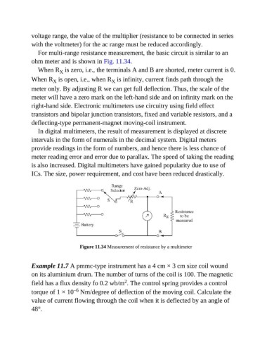
                  For multi-range resistance measurement, the basic circuit is similar to an

               ohm meter and is shown in Fig. 11.34.
                  When R  is zero, i.e., the terminals A and B are shorted, meter current is 0.
                            X
               When R  is open, i.e., when R  is infinity, current finds path through the
                                                    X
                         X
               meter only. By adjusting R we can get full deflection. Thus, the scale of the
               meter will have a zero mark on the left-hand side and on infinity mark on the

               right-hand side. Electronic multimeters use circuitry using field effect
               transistors and bipolar junction transistors, fixed and variable resistors, and a
               deflecting-type permanent-magnet moving-coil instrument.

                  In digital multimeters, the result of measurement is displayed at discrete
               intervals in the form of numerals in the decimal system. Digital meters

               provide readings in the form of numbers, and hence there is less chance of
               meter reading error and error due to parallax. The speed of taking the reading

               is also increased. Digital multimeters have gained popularity due to use of
               ICs. The size, power requirement, and cost have been reduced drastically.


                                      Figure 11.34 Measurement of resistance by a multimeter


               Example 11.7 A pmmc-type instrument has a 4 cm × 3 cm size coil wound
               on its aluminium drum. The number of turns of the coil is 100. The magnetic
                                                          2
               field has a flux density fo 0.2 wb/m . The control spring provides a control
                                   –6
               torque of 1 × 10  Nm/degree of deflection of the moving coil. Calculate the
               value of current flowing through the coil when it is deflected by an angle of
               48°.

