


Page 860 - Basic Electrical Engineering
P. 860
It is seen from Fig. 11.31 that the there exists an angle of phase difference
               of θ between I  and nI . Idealy nI  and I  should not have any phase angle
                                 1
                                          2
                                                       2
                                                               1
               between them.
                  We have seen that there exists a difference between the actual
               transformation ratio and the turns ratio of a CT. This largely depends upon
               the loss component of the no-load current, i.e., I . The transformer phase
                                                                         c
               angle depends upon the magnetizing component of the no-load current, i.e.,
               I . By proper design, the magnitude of I  and I  are kept low to maintain the
                m
                                                                        m
                                                                c
               ratio error and phase angle error to the minimum.


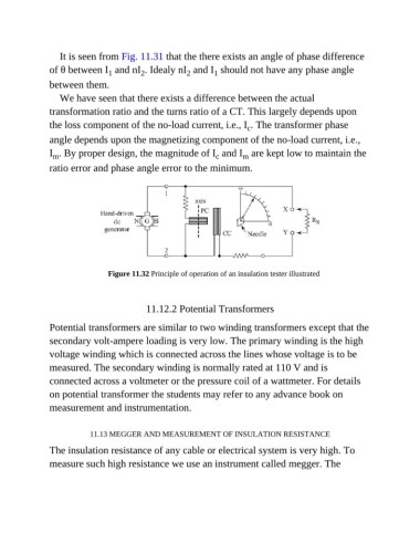
                                Figure 11.32 Principle of operation of an insulation tester illustrated


                                            11.12.2 Potential Transformers

               Potential transformers are similar to two winding transformers except that the
               secondary volt-ampere loading is very low. The primary winding is the high

               voltage winding which is connected across the lines whose voltage is to be
               measured. The secondary winding is normally rated at 110 V and is

               connected across a voltmeter or the pressure coil of a wattmeter. For details
               on potential transformer the students may refer to any advance book on

               measurement and instrumentation.


                           11.13 MEGGER AND MEASUREMENT OF INSULATION RESISTANCE
               The insulation resistance of any cable or electrical system is very high. To

               measure such high resistance we use an instrument called megger. The

