


Page 999 - Basic Electrical Engineering
P. 999
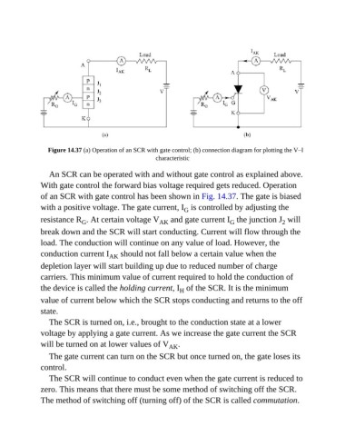
Figure 14.37 (a) Operation of an SCR with gate control; (b) connection diagram for plotting the V–I
                                                        characteristic


                  An SCR can be operated with and without gate control as explained above.
               With gate control the forward bias voltage required gets reduced. Operation

               of an SCR with gate control has been shown in Fig. 14.37. The gate is biased
               with a positive voltage. The gate current, I  is controlled by adjusting the
                                                                  G
               resistance R . At certain voltage V       AK   and gate current I  the junction J  will
                              G
                                                                                                     2
                                                                                   G
               break down and the SCR will start conducting. Current will flow through the
               load. The conduction will continue on any value of load. However, the

               conduction current I     AK  should not fall below a certain value when the
               depletion layer will start building up due to reduced number of charge

               carriers. This minimum value of current required to hold the conduction of
               the device is called the holding current, I  of the SCR. It is the minimum
                                                                 H
               value of current below which the SCR stops conducting and returns to the off
               state.

                  The SCR is turned on, i.e., brought to the conduction state at a lower
               voltage by applying a gate current. As we increase the gate current the SCR

               will be turned on at lower values of V        AK .
                  The gate current can turn on the SCR but once turned on, the gate loses its

               control.
                  The SCR will continue to conduct even when the gate current is reduced to

               zero. This means that there must be some method of switching off the SCR.
               The method of switching off (turning off) of the SCR is called commutation.

