


Page 1004 - Basic Electrical Engineering
P. 1004
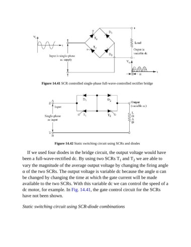
Figure 14.41 SCR controlled single-phase full-wave-controlled rectifier bridge


                                    Figure 14.42 Static switching circuit using SCRs and diodes

                  If we used four diodes in the bridge circuit, the output voltage would have

               been a full-wave-rectified dc. By using two SCRs T  and T  we are able to
                                                                                      2
                                                                              1
               vary the magnitude of the average output voltage by changing the firing angle
               α of the two SCRs. The output voltage is variable dc because the angle α can
               be changed by changing the time at which the gate current will be made

               available to the two SCRs. With this variable dc we can control the speed of a
               dc motor, for example. In Fig. 14.41, the gate control circuit for the SCRs

               have not been shown.


               Static switching circuit using SCR-diode combinations

