


Page 1003 - Basic Electrical Engineering
P. 1003
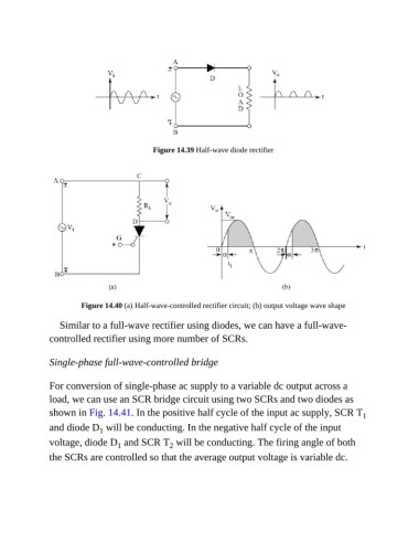
Figure 14.39 Half-wave diode rectifier


                         Figure 14.40 (a) Half-wave-controlled rectifier circuit; (b) output voltage wave shape


                  Similar to a full-wave rectifier using diodes, we can have a full-wave-
               controlled rectifier using more number of SCRs.


               Single-phase full-wave-controlled bridge


               For conversion of single-phase ac supply to a variable dc output across a
               load, we can use an SCR bridge circuit using two SCRs and two diodes as

               shown in Fig. 14.41. In the positive half cycle of the input ac supply, SCR T               1
               and diode D  will be conducting. In the negative half cycle of the input
                              1
               voltage, diode D  and SCR T  will be conducting. The firing angle of both
                                                   2
                                   1
               the SCRs are controlled so that the average output voltage is variable dc.

