
Page 172 - Fiber Optic Communications Fund
P. 172
Optical Modulators and Modulation Schemes 153
With Δ = ∕2,
∕2 × 1530 × 10 −9 × 10 × 10 −6
V = V
3
× 5 × 10 −2 ×(2.2) ×(30 × 10 −12 )
= 0.47 V.
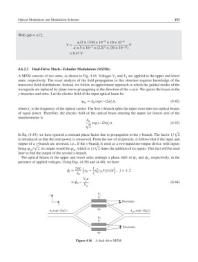
4.6.2.2 Dual-Drive Mach–Zehnder Modulators (MZMs)
A MZM consists of two arms, as shown in Fig. 4.16. Voltages V and V are applied to the upper and lower
2
1
arms, respectively. The exact analysis of the field propagation in this structure requires knowledge of the
transverse field distributions. Instead, we follow an approximate approach in which the guided modes of the
waveguide are replaced by plane waves propagating in the direction of the x-axis. We ignore the losses in the
y-branches and arms. Let the electric field of the input optical beam be
= A exp (−i2f t), (4.42)
in 0 c
where f is the frequency of the optical carrier. The first y-branch splits the input wave into two optical beams
c
of equal power. Therefore, the electric field of the optical beam entering the upper (or lower) arm of the
interferometer is
A 0
√ exp (−i2f t). (4.43)
c
2
√
In Eq. (4.43), we have ignored a constant phase factor due to propagation in the y-branch. The factor 1∕ 2
is introduced so that the total power is conserved. From the law of reciprocity, it follows that if the input and
output of a y-branch are reversed, i.e., if the y-branch is used as a two-input/one-output device with inputs
√ √
being ∕ 2, its output would be , which is 1∕ 2 times the addition of its inputs. This fact will be used
in in
later to find the output of the second y-branch.
The optical beams in the upper and lower arms undergo a phase shift of and , respectively, in the
2
1
presence of applied voltages. Using Eqs. (4.38) and (4.40), we have
2L ( 1 3 )
= n − n r V (t)∕d , j = 1, 2
j 0 0 33 j
2
0
V
j
= − . (4.44)
0
V
z V 1
Electrodes
x
A 0 exp(–i2πf c t) A out exp(–i2πf c t)
V 2
Electrodes
Figure 4.16 A dual-drive MZM.