Page 177 - Fiber Optic Communications Fund
P. 177

158                                                               Fiber Optic Communications


            where P is the input power; the extinction ratio is
                   0
                                                 P max  exp (− L)
                                                              0
                                              =     =          .                            (4.72)
                                                 P min  exp (− L)
                                                              1
            To obtain the optimum performance, a high extinction ratio is desirable. To achieve this, typically InP-based
            semiconductors are used for 1300-nm or 1550-nm applications.
              The absorption coefficient can be changed significantly by applying a relatively lower driving voltage.
            Therefore, the EAMs are very effective and the size could be quite small. The length of EAMs is typically
            200 mm, whereas that of electro-optic modulators is a few centimeters. EAMs can easily be integrated with
            the laser diode, since both are based on similar semiconductor materials. The drawbacks of EAMs are as
            follows. (i) They have residual chirps similar to directly modulated lasers. The interaction of the chirp and
            fiber dispersion could lead to enhanced pulse broadening. (ii) The extinction ratio is typically ≤ 10 dB, which
            could lead to a power penalty [8].


            4.7 Optical Realization of Modulation Schemes

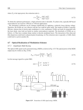
            4.7.1   Amplitude-Shift Keying
            The optical ASK signal can be generated using a MZM, as shown in Fig. 4.19. The optical power of the MZM
            output may be written as (Eq. (4.56))
                                                     [             ]
                                                       m(t)  V bias 
                                                    2
                                          P   = P cos       −       .                         (4.73)
                                           out   0
                                                        V      2V
                                                               
            Let the message signal be a polar NRZ,
                                                   {
                                                     +V  for bit ‘1’
                                             m(t)=                .                           (4.74)
                                                     −V  for bit ‘0’


                              Voltage  1 10  1  0  1  NRZ data      Power  1 10  1  0  1


                                                 t
                                                                                         t

                                                                   ASK signal


                       Laser                                          1  1  0  1  0  1
                                                                    Field
                                                 MZM
                                                                                        t


                                    Figure 4.19  Generation of ASK signal using a MZM.
   172   173   174   175   176   177   178   179   180   181   182