
Page 182 - Fiber Optic Communications Fund
P. 182
Optical Modulators and Modulation Schemes 163
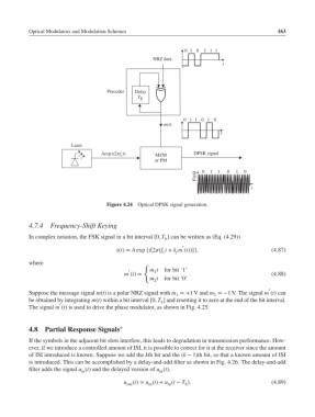
01 0 1 1 1
NRZ data
t
Precoder Delay
T
b
01 1 0 1 0
m(t)
t
Laser
Aexp(i2πf c t) MZM DPSK signal
or PM
Field 0 1 1 0 1 0
t
Figure 4.24 Optical DPSK signal generation.
4.7.4 Frequency-Shift Keying
In complex notation, the FSK signal in a bit interval [0, T ] can be written as (Eq. (4.29))
b
′
s(t)= A exp {i[2(f t + k m (t))]}, (4.87)
f
c
where
{
′ m t for bit ‘1’
1
m (t)= . (4.88)
m t for bit ‘0’
2
′
Suppose the message signal m(t) is a polar NRZ signal with m =+1 V and m =−1 V. The signal m (t) can
1
2
be obtained by integrating m(t) within a bit interval [0, T ] and resetting it to zero at the end of the bit interval.
b
′
The signal m (t) is used to drive the phase modulator, as shown in Fig. 4.25.
4.8 Partial Response Signals ∗
If the symbols in the adjacent bit slots interfere, this leads to degradation in transmission performance. How-
ever, if we introduce a controlled amount of ISI, it is possible to correct for it at the receiver since the amount
of ISI introduced is known. Suppose we add the kth bit and the (k − 1)th bit, so that a known amount of ISI
is introduced. This can be accomplished by a delay-and-add filter as shown in Fig. 4.26. The delay-and-add
filter adds the signal u (t) and the delayed version of u (t),
in in
u (t)= u (t)+ u (t − T ). (4.89)
in
out
b
in