
Page 180 - Fiber Optic Communications Fund
P. 180
Optical Modulators and Modulation Schemes 161
Let the message signal be a polar NRZ given by Eq. (4.74). The desired field envelope of the Mach–Zehnder
output is
{
+A 0 for bit ‘1’
A out = . (4.83)
−A for bit ‘0’
0
For bit ‘1’, substituting Eq. (4.74) in Eq. (4.82) and using Eq. (4.83), we obtain
[ ]
V V bias
A cos − = A ,
0
0
V 2V
V V bias
− = 2j, j = 0, ±1, ±2, … (4.84)
V 2V
Similarly, for bit ‘0’, we have
[ ]
−V V bias
A cos − =−A ,
0 0
V 2V
V V bias
− − =(2l + 1), l = 0, ±1, ±2, … (4.85)
V 2V
Simplifying Eqs. (4.84) and (4.85), we obtain
[2(j − l)− 1]V
V = ,
2
V =−[2(j + l)+ 1]V . (4.86)
bias
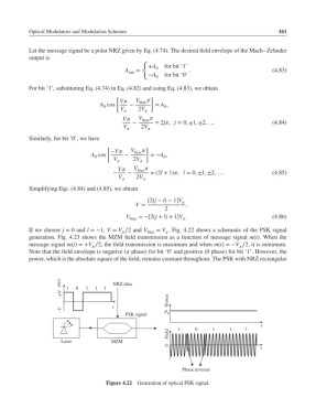
If we choose j = 0 and l =−1, V = V ∕2 and V bias = V . Fig. 4.22 shows a schematic of the PSK signal
generation. Fig. 4.23 shows the MZM field transmission as a function of message signal m(t). When the
message signal m(t)=+V ∕2, the field transmission is maximum and when m(t)=−V ∕2, it is minimum.
Note that the field envelope is negative ( phase) for bit ‘0’ and positive (0 phase) for bit ‘1’. However, the
power, which is the absolute square of the field, remains constant throughout. The PSK with NRZ rectangular
m(t) NRZ data
1 0 1 1 1
+V
Power
–V t
PSK signal P 0
t
1
0
1
1
1
Field
Laser MZM
0
t
Phase reversal
Figure 4.22 Generation of optical PSK signal.