
Page 365 - Fiber Optic Communications Fund
P. 365
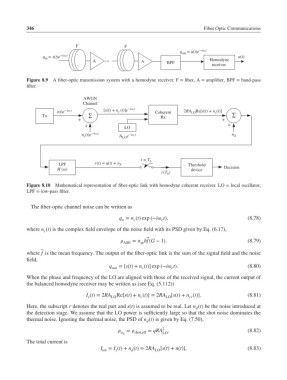
346                                                               Fiber Optic Communications


                               F                F
                                                                     q out  = u(t)e *iω c t
                  q in  = s(t)e *iω c t                                                   u(t)
                                     A   …             A        BPF             Homodyne
                                                                                 receiver

            Figure 8.9 A fiber-optic transmission system with a homodyne receiver. F = fiber, A = amplifier, BPF = band-pass
            filter.

                                 AWGN
                                 Channel
                                              c
                        s(t)e *iω c t    [s(t) + n (t)]e *iω c t  Coherent  2RA Re[s(t) + n (t)]
                                                                                  c
                                                                         LO
                  Tx               ∑                          Rx                        ∑
                               +                                                    +
                                  +                                                   +
                                                LO
                                 n (t)e *iω c t  A e *iω c t                            n d
                                  c
                                                LO
                                                       t = T b
                        LPF          r(t) = u(t) + n F                  Threshold
                        H (ω)                                            device      Decision
                                                              r(T )
                                                                b
            Figure 8.10  Mathematical representation of fiber-optic link with homodyne coherent receiver. LO = local oscillator,
            LPF = low-pass filter.


              The fiber-optic channel noise can be written as

                                               q = n (t) exp (−i t),                        (8.78)
                                                    c
                                                n
                                                              c
            where n (t) is the complex field envelope of the noise field with its PSD given by Eq. (6.17),
                   c
                                                ASE  = n hf(G − 1).                         (8.79)
                                                      sp
            where f is the mean frequency. The output of the fiber-optic link is the sum of the signal field and the noise
            field,
                                           q  =[s(t)+ n (t)] exp (−i t).                    (8.80)
                                            out        c          c
            When the phase and frequency of the LO are aligned with those of the received signal, the current output of
            the balanced homodyne receiver may be written as (see Eq. (5.112))
                                  I (t)= 2RA  Re[s(t)+ n (t)] = 2RA  [s(t)+ n (t)].           (8.81)
                                   s        LO        c         LO      cr
            Here, the subscript r denotes the real part and s(t) is assumed to be real. Let n (t) be the noise introduced at
                                                                           d
            the detection stage. We assume that the LO power is sufficiently large so that the shot noise dominates the
            thermal noise. Ignoring the thermal noise, the PSD of n (t) is given by Eq. (7.50),
                                                         d
                                                              2
                                                =    = qRA  .                             (8.82)
                                               n d  shot,eff  LO
            The total current is
                                        I tot  = I (t)+ n (t)= 2RA LO [s(t)+ n(t)],           (8.83)
                                                   d
                                             s