Page 370 - Fiber Optic Communications Fund
P. 370

Performance Analysis                                                               351


           For signals such as OOK, the information is contained only in the amplitude and if a detection scheme ignores
           the phase of the received signal, it does not lead to the loss of information. Such a scheme is known as asyn-
           chronous detection. For example, if the received signal passes through an envelope detector, the phase infor-
           mation is lost and the transmitted information is retrieved asynchronously without having to track the phase
           of the received signal. In non-optical communication, asynchronous receivers are known as non-coherent
           receivers [1, 2]. In contrast, a detector can detect the phase of the transmitted signal by carefully aligning the
           phase of the microwave oscillator (or equivalently synchronizing the timings of the oscillator output) with the
           received signal and such a scheme is known as synchronous detection. For PSK signals, a synchronous detec-
           tor has to be used. For homodyne receivers, asynchronous detection schemes can be realized by introducing
           an envelope detector in the DSP unit. The performance of modulation schemes with homodyne asynchronous
           detection is similar to the corresponding heterodyne receivers.


           8.4.1  PSK: Synchronous Detection

           The received signal in the absence of noise can be written as
                                                  {
                                                    I (t) for ‘1’
                                                     1
                                             I(t)=                                         (8.124)
                                                    I (t) for ‘0’
                                                     0
           where
                                      I (t)= s (t) cos ( t +Δ),  j = 0, 1,             (8.125)
                                       j
                                                    IF
                                             j
           with s (t)=−s (t). We assume that s(t) is real. The filter matched to I(t) is (see Eq. (8.40))
               0
                       1
                                             ̃ ∗
                                      ̃ ∗
                               H ()=[I ()− I ()] exp (iT )
                                I      1     0           b
                                                      ∗
                                       ∗
                                    =[̃s ( −  )e iΔ  + ̃s ( +  )e −iΔ ] exp (iT ).  (8.126)
                                       1      IF      1     IF             b
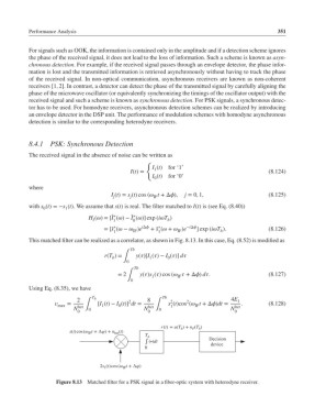
           This matched filter can be realized as a correlator, as shown in Fig. 8.13. In this case, Eq. (8.52) is modified as
                                             Tb
                                    r(T )=    y()[I ()− I ()] d
                                       b  ∫        1     0
                                           0
                                              Tb
                                        = 2     y()s () cos (  +Δ) d.          (8.127)
                                            ∫       1       IF
                                             0
           Using Eq. (8.35), we have
                                                       Tb
                                T b
                           2                2     8       2    2              4E 1
                     =          [I (t)− I (t)] dt =    s (t)cos ( t +Δ)dt =  .       (8.128)
                    max    het ∫   1     0         het ∫  1       IF            het
                          N    0                 N    0                       N
                           0                       0                            0
                                                       r(t) = u(T ) + n (T )
                                                              b
                                                                    b
                                                                 F
                        s(t)cos(ω t + ∆φ) + n (t)
                               IF
                                       het
                                                  T b
                                                  ʃ (∙)dt              Decision
                                                                        device
                                                 0
                                  2s 1 (t)cos(ω IF t + ∆φ)
                    Figure 8.13  Matched filter for a PSK signal in a fiber-optic system with heterodyne receiver.
   365   366   367   368   369   370   371   372   373   374   375