Page 394 - Fiber Optic Communications Fund
P. 394

Performance Analysis                                                               375


           the optical carrier (or it should be post-corrected using the DSP). In contrast, for systems based on DPSK, the
           transmitted signal of the previous bit interval acts as a reference and, therefore, there is no need for the local
           oscillator and the phase synchronization. However, one of the drawbacks is that the phase of the previous bit
           is noisy and, therefore, this leads to performance degradation for DPSK compared with PSK.
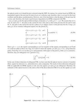
            Let s (t) and s (t) be the optical field envelopes of duration ≤ T with s (t)=−s (t). We assume that s(t) is
                                                              b
                                                                    0
                1
                       0
                                                                            1
           real. To send a bit ‘1’, the pulse in the current bit slot is the same as that in the previous bit slot and to send
           bit ‘0’, the pulse in the current bit slot has a phase of ± radians relative to the previous bit slot. Using s (t)
                                                                                              1
           and s (t), let us construct orthogonal signals over the period 2T :
               0
                                                             b
                                  ′
                                 s (t)= s (t)+ s (t − T )  set I  ⎫
                                  1     1     1    b
                                                             ⎪
                                 or                          ⎬  to send bit ‘1’;           (8.299)
                                  ′
                                 s (t)= s (t)+ s (t − T )  set II  ⎪
                                              0
                                                   b
                                        0
                                  1                          ⎭
                                  ′
                                 s (t)= s (t)+ s (t − T ) set I  ⎫
                                  0     1     0    b
                                                             ⎪
                                 or                          ⎬  to send bit ‘0’.           (8.300)
                                  ′
                                 s (t)= s (t)+ s (t − T ) set II  ⎪
                                  0     0     1    b         ⎭
           Since s (t)=−s (t), the signals corresponding to set I are negative of the signals corresponding to set II and
                0       1                                                 ′
           we could use either of these sets. Figs. 8.22 and 8.23 show the signals s (t) and s (t), j = 0, 1, using Gaussian
                                                                   j      j
                                       ′
                                                                                   ′
           pulses. From Fig. 8.23, we see that s (t) is antisymmetric with respect to the point T while s (t) is symmetric;
                                       0                                    b      1
           therefore, they are orthogonal over a period of 2T :
                                                  b
                                                           2
                                            |  2T b       |
                                                      ′
                                                  ′
                                            |    s (t)s (t)dt| = 0.                        (8.301)
                                                          |
                                            |
                                            |∫    1   0   |
                                            |  0          |
           In the case of direct detection of orthogonal FSK, we have seen that the optical receiver consists of matched
           filters, square-law detectors (i.e., photodetectors), and a comparator. The results of direct detection orthogonal
                                                              ′
                                                                      ′
           FSK are applicable for DPSK signals as well, since the signals s (t) and s (t) are orthogonal. Therefore, the
                                                              1       0
                                                                                           ′
           schematic of the optical receiver is the same as that of the direct detection FSK if we use the signals s (t) and
                                                                                           1
               s 1 (t)                                  s 0 (t)
                                                        0                                 T b
              0                                     t                                        t
                                                 T b
                                Figure 8.22  Optical complex field envelopes s (t) and s (t).
                                                                  1      0
   389   390   391   392   393   394   395   396   397   398   399