
Page 471 - Fiber Optic Communications Fund
P. 471
452 Fiber Optic Communications
signals signals
FWM FWM
tones tones
0 Δf 2Δf 3Δf 4Δf 0 Δf 2Δf 3Δf
(a) (b)
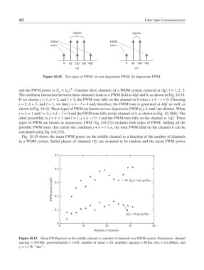
Figure 10.18 Two types of FWM: (a) non-degenerate FWM; (b) degenerate FWM.
2
and the FWM power is P = | | . Consider three channels of a WDM system centered at lΔf, l = 1, 2, 3.
n
n
The nonlinear interaction between these channels leads to a FWM field at 4Δf and 0, as shown in Fig. 10.18.
If we choose j = 1, k = 2, and l = 3, the FWM tone falls on the channel at 0 since j + k − l = 0. Choosing
j = 2, k = 3, and l = 1, we find j + k − l = 4 and, therefore, the FWM tone is generated at 4Δf as well, as
shown in Fig. 10.18. These types of FWM are known as non-degenerate FWM as j, k, and l are distinct. When
j = k = 1 and l = 2, j + k − l = 0 and the FWM tone falls on the channel at 0, as shown in Fig. 10.18(b). The
other possibility is j = k = 2 and l = 1, j + k − l = 3 and the FWM tone falls on the channel at 3Δf. These
types of FWM are known as degenerate FWM. Eq. (10.232) includes both types of FWM. Adding all the
possible FWM tones that satisfy the condition j + k − l = n, the total FWM field on the channel n can be
calculated using Eq. (10.232).
Fig. 10.19 shows the mean FWM power on the middle channel as a function of the number of channels
in a WDM system. Initial phases of channels ( ) are assumed to be random and the mean FWM power
j
0.5
0.4
FWM power (mW) 0.3 ∣β 2 ∣ = 6 ps.ps/km
0.2
0.1
∣β 2 ∣ = 10 ps.ps/km
0
0 10 20 30 40
Number of channels
Figure 10.19 Mean FWM power on the middle channel vs. number of channels in a WDM system. Parameters: channel
spacing = 50 GHz, power/channel = 3 mW, number of spans = 20, amplifier spacing = 80 km, loss = 0.2 dB/km, and
−1
= 1.1W −1 km .