Page 1260 - 2006 HARLEY FLSTCI SERVICE MANUAL
P. 1260

8-3
                                        7


                                    6                                                                                                                    2006 FLSTFSE 2 : Electrical


                                                                                                                    NOTE If complete turn signal is being replaced follow TURN SIG- NAL INSTALLATION. If only socket assembly is being replaced follow DISASSMBLY/ASSEMBLY OF SOCKET  and crimp on new socket terminals.
                              5                                                                                                    Lay old turn signal lamp next to new turn signal lamp and Strip 3/16 inch (4.8 mm) of insulation off new lamp wires


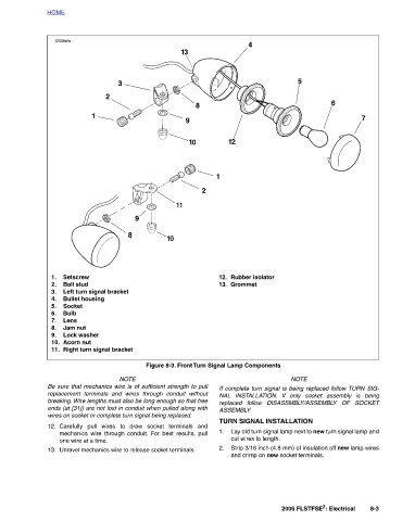
                                                                                      Rubber isolator                           TURN SIGNAL INSTALLATION  cut wires to length.


                   4                                                                    Grommet


                                               12                                                                            ASSEMBLY
                                                                                      12.  13.                                     1.   2.
                                                         1                                                      Figure 8-3. Front Turn Signal Lamp Components

                                                             2
                                     8
                                               10
                     13                  9
                                                                  11
                                                                           10


                                                                     9                                                           Carefully pull wires to draw socket terminals and mechanics wire through conduit. For best results, pull
                                                                          8                                         NOTE  Be sure that mechanics wire is of sufficient strength to pull replacement terminals and wires through conduit without breaking. Wire lengths must also be long enough so that free ends (at [31]) are not lost in conduit when pulled along with  Unravel mechanics wire to release socket terminals.
                              3                                                                                               wires on socket or complete turn signal being replaced.
                                  2

                                        1                                                 Left turn signal bracket  Right turn signal bracket
                                                                                      Setscrew  Ball stud  Bullet housing  Socket  Bulb  Lens  Jam nut  Lock washer  Acorn nut  one wire at a time.


          HOME    f2098x8x                                                            1.  2.  3.  4.  5.  6.  7.  8.  9.  10.  11.  12.  13.
   1255   1256   1257   1258   1259   1260   1261   1262   1263   1264   1265