
Page 885 - 2006 HARLEY FLSTCI SERVICE MANUAL
P. 885
3.26 2
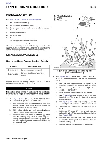
Figure 3-128. Connecting Rod Clamping Tool
(Part No. HD-95952-33C) Insert threaded rod through upper rod bushing.
3 Obtain the CONNECTING ROD The driver is stamped to ensure
1 3 BUSHING REMOVER/INSTALLER (Part No. HD-95970- Sparingly apply graphite lubricant to threads of rod to prolong service life and ensure smooth operation. Slide receiver cup (6) onto threaded rod (2) with the d. See Figure 3-130. Slide remover side of driver down See Figure 3-129. Slide Nice bearing (4) and flat washer (3) down threaded rod until it contacts driver. Thread the hex cylinder onto rod until assembly is Holding nut (7) with a 5/8 in. box wrench, turn hex cylinder (1) with a 5/8 in. socket until bushing is free. Unthread hex cylinder from rod. Remove flat was
Threaded cylinders Clamp Thumbscrew 1 2 Figure 3-129. closed side facing nut (7). threaded rod. proper orientation. snug. See Figure 3-132. rod from bushing bore.
1. 2. 3. d0189x3x See 32D). a. b. c. e. f. g. h. i.
2. Obtain the CONNECTING ROD
UPPER CONNECTING ROD
REMOVAL OVERVIEW See 3.16 TOP END OVERHAUL: DISASSEMBLY. Remove breather assembly. Remove rocker arm support plate. Remove push rods and push rod covers. Do not remove lifters or lifter covers. Remove cylinder head. Remove cylinder. Remove piston. Service upper connecting rod bushing. NOTE Service of connecting rods is limited to replacement of the upper bushing. Damage to connecting rods or lower bushing service requires replacement of the flywheel assembly. DISASSEMBLY/ASSEMBLY Removing Upper Connecting Rod Bushing SPECIALTY TOOL Connecting rod clamping tool Connecting rod bushing remover/ installer NOTE Replace the upper rod b
HOME 1. 2. 3. 4. 5. 6. 7. PART NO. HD-95952-33C HD-95970-32D crankcase. See 1. a. b. c. 3-98