Page 890 - 2006 HARLEY FLSTCI SERVICE MANUAL
P. 890

3.27       2                                                              24  23            22            21                                      3-103


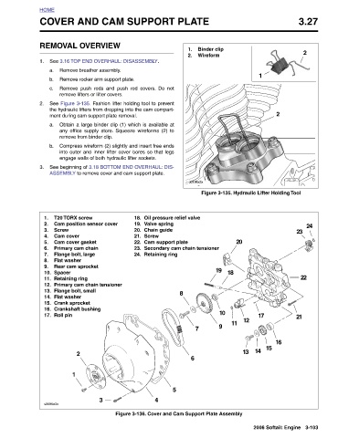
                                                                            Figure 3-135. Hydraulic Lifter Holding Tool


                                                2                                                                                  16                            2006 Softail: Engine
                                                                                                                                     15

                                  1                                                                                      17
                                                                                                                                      14
                                                                                                                           12         13
                                                                                              20
                                                                                                         18             10  11  9
                        Binder clip  Wireform                                                            19

               COVER AND CAM SUPPORT PLATE
                                                                                     Oil pressure relief valve  Valve spring  Chain guide  Cam support plate  Retaining ring  5  4 Figure 3-136. Cover and Cam Support Plate Assembly
                        1.  2.                                           d0196x3x               Secondary cam chain tensioner  8  7     6


                                                           Compress wireform (2) slightly and insert free ends
                                                                   See beginning of 3.18 BOTTOM END OVERHAUL: DIS-
                                                              into outer and inner lifter cover bores so that legs
                                                      any office supply store. Squeeze wireforms (2) to
                                            See Figure 3-135. Fashion lifter holding tool to prevent
                                       Remove push rods and push rod covers. Do not
                                                    Obtain a large binder clip (1) which is available at
                                              the hydraulic lifters from dropping into the cam compart-
                                                                                     18.  19.  20.  Screw  21.  22.  23.  24.


                       REMOVAL OVERVIEW See 3.16 TOP END OVERHAUL: DISASSEMBLY.  Remove breather assembly. Remove rocker arm support plate.  remove lifters or lifter covers.  ment during cam support plate removal.  remove from binder clip.   engage walls of both hydraulic lifter sockets.  ASSEMBLY to remove cover and cam support plate.  T20 TORX screw Cam position sensor cover  Cam cover  Cam cover gasket  Primary cam chain  Flange bolt, large  Flat washer  Rear cam sprocket  Retaining ring Primary cam chain tensioner  Flange bolt, small  Flat washer  Crank sprocket  Crankshaft bushing  2  1  3


          HOME               1.  a.   b.   c.   2.  a.     b.      3.                1.  2.  Screw  3.  4.  5.  6.  7.  8.  9.  Spacer  10.  11.  12.  13.  14.  15.  16.  Roll pin  17.  s0595a3x


        3
   885   886   887   888   889   890   891   892   893   894   895